
Method for determining ion concentration and energy of shallow junction implants

a technology of ion concentration and energy, applied in the direction of optical radiation measurement, polarisation-affecting properties, instruments, etc., can solve the problems of affecting the extent of damage to the lattice, the above-mentioned techniques do not function to measure ion concentration directly, and the damage is more extensiv

Inactive Publication Date: 2005-06-30
THERMA WAVE INC
View PDF17 Cites 10 Cited by
  • Summary
  • Abstract
  • Description
  • Claims
  • Application Information

AI Technical Summary

Benefits of technology

"The invention combines the output from both a thermal wave type measurement and a spectroscopic measurement (reflectometry or broadband ellipsometry) to accurately depth profile crystalline damage and implanted ion distribution right after implantation. The sample is periodically excited using an intensity modulated pump beam, and the resulting optical reflectivity, vertical displacement, angular displacement, and periodic ellipsometric effects are measured. The first and second signals are combined to evaluate the dosage level and energy of the implant using a theoretical model of the sample. Additional measurements may be made to improve the analysis, such as using both reflectometry and spectroscopic ellipsometry methods. The invention provides a metrology tool that combines various measurement techniques on a single platform."

Problems solved by technology

The above described techniques do not function to measure ion concentration directly, rather, they measure the damage done to the crystal lattice structure by the implanted ions.
Variations in the energy used to implant the ions also affects the extent of damage to the lattice.
As the energy level is increased, the ions are driven deeper into the lattice and the damage is more extensive.
Any unexpected variations in either dosage level or energy of the implant can result in the failure of the circuit.
Some attempts for non-destructive analysis have been made with ion scattering and spectroscopic ellipsometry, while the non-destructive thermal wave methods have demonstrated low sensitivity for implants below 5 keV.
Most SIMS equipment have a physical limitation for accurate depth profiling of ultra-shallow junctions.
The ion scattering methods are restricted to give the depth distribution of the displaced silicon atoms only and have been found to lack the sensitivity to detect defects at levels which are important in device operation.
Spectroscopic ellipsometry has been used with simple 1-2 layer models with effective medium approach for layer mixing, which complicates the analyses as separate recipes are needed for high and low (<2.5 keV) ion implants.

Method used


Image

  • Method for determining ion concentration and energy of shallow junction implants
  • Method for determining ion concentration and energy of shallow junction implants
  • Method for determining ion concentration and energy of shallow junction implants

Examples


Embodiment Construction

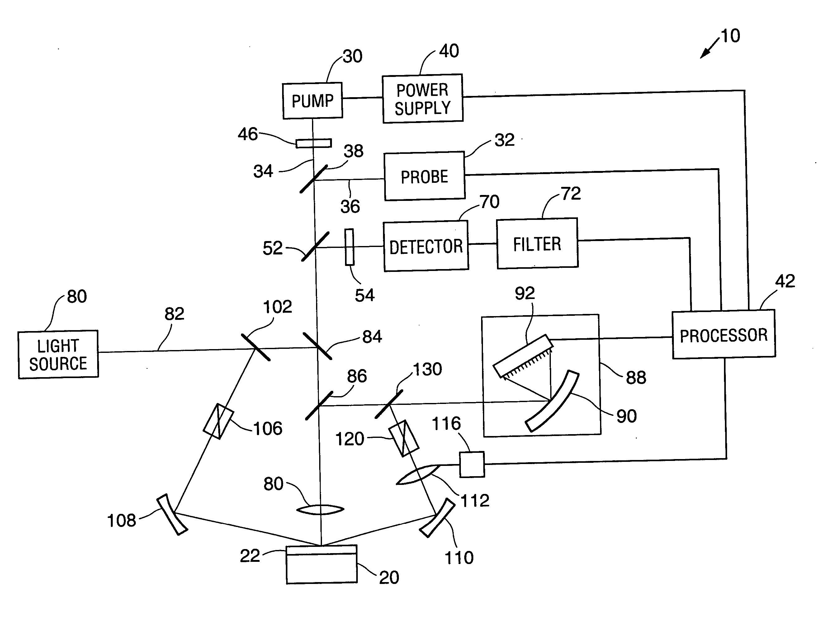
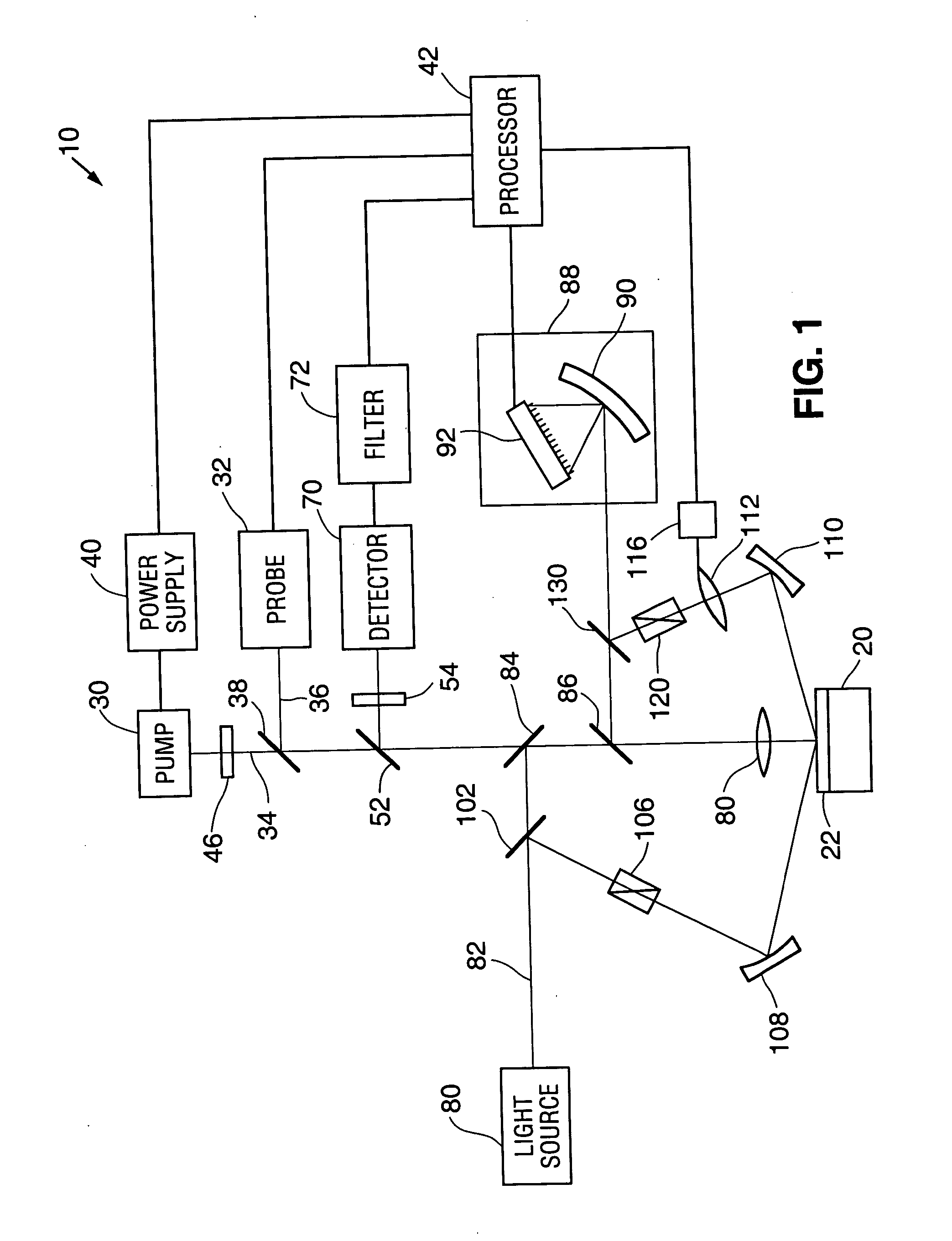
[0024]FIG. 1 is a simplified diagram of the basic components of an apparatus 10 which can be used to take the measurements useful in applying the methods of the subject invention. The apparatus is particularly suited for measuring characteristics of semiconductor wafers 20. In one important aspect of the invention, the device is used to evaluate ion implantations in the wafer. In particular, the device is used to characterize both the dose and energy levels of the implanted ions.

[0025] In accordance with the subject invention, the apparatus includes a first measurement system for generating thermal and / or plasma wavers and monitoring the propagation of these waves in the sample. This portion of the system includes a pump laser 30 for exciting the sample and a probe laser 32 for monitoring the sample. Gas, solid state or semiconductor lasers can be used. As described in the assignee's earlier patents, other means for exciting the sample can include different sources of electromagnet...


PUM

PropertyMeasurementUnit
modulation frequencyaaaaaaaaaa
diameteraaaaaaaaaa

Abstract

A method is disclosed for measuring the dose and energy level of ion implants forming a shallow junction in a semiconductor sample. In the method, two independent measurements of the sample are made. The first measurement monitors the response of the sample to periodic excitation. In the illustrated embodiment, the modulated optical reflectivity of a reflected probe beam is monitored to provide information related to the generation of thermal and / or plasma waves in the sample. A second spectroscopic measurement is also performed. This measurement could be either a spectroscopic reflectometry measurement or a spectroscopic ellipsometry measurement. The data from the two measurements are combined in a manner to yield information about both the dose (concentration) of the dopants as well as the energy used to inject the dopants in the semiconductor lattice. The method will useful in controlling the formation of shallow junctions.

Description

PRIORITY [0001] This application is a divisional of U.S. patent application Ser. No. 10 / 689,332, filed Oct. 20, 2003, which was in turn a divisional of U.S. patent application Ser. No. 10 / 341,225, filed Jan. 13, 2003, which was in turn a divisional of U.S. patent application Ser. No. 09 / 884,262, filed Jun. 19, 2001, which claims priority from provisional application Ser. No. 60 / 218,594, filed Jul. 17, 2000, each of which is incorporated herein by reference.TECHNICAL FIELD [0002] The subject invention relates to a method for evaluating the characteristics of shallow junctions formed on semiconductor wafers. More specifically, the invention relates to the optical inspection of shallow junctions and the determination of energy and dose of the implants used to create the shallow junction. BACKGROUND OF THE INVENTION [0003] The use of optical inspection methods to evaluate ion implants has been well known for some time. Successful measurements have been made with equipment in which an in...

Claims


Application Information

Patent Timeline
Patent Type & Authority Applications(United States)
IPC IPC(8): G01N21/17G01N21/21
CPCG01N21/211G01N21/171
Inventor HOVINEN, MINNAOPSAL, JON
Owner THERMA WAVE INC
Learn More