
Macro lens

a micro lens and lens body technology, applied in the field of micro lenses, can solve the problems of reducing the total length of the lens system, limiting the use of micro lenses, and increasing the displacement of lenses accordingly

Inactive Publication Date: 2005-06-30
TAMRON
View PDF2 Cites 24 Cited by
  • Summary
  • Abstract
  • Description
  • Claims
  • Application Information

AI Technical Summary

Problems solved by technology

Many macro lenses with the floating mechanism are typically based upon Gauss lens system, and their focal lengths are as short as 50 mm which is insufficient to attain the wide-angle.
Some macro lenses are of more reduced focal length but are restricted in their uses because they are photography lenses for the close image pickup range only, improper to the infinite photography that are the most frequent use.
The macro lenses as disclosed in Patent Documents 1 and 2 commonly employ the floating mechanism, but they are disadvantageous in that a greater displacement of lenses accordingly increases the total length of the lens system.
In addition, a diameter of the lenses is increased to ensure a sufficient amount of peripheral light, and this causes an adverse effect to deteriorate compactness and portability.
In the disclosures of Patent Documents 1 and 2, the second lens group has a reduced power to avoid the supposed degradation of the usefulness of the Gauss lens system due to the loss of symmetry of the lenses about the aperture stop, and this causes an additional problem of a greater displacement of the lenses for focusing.
Exceeding the lower limit defined in the formula, it is hard to ensure backfocus because of the diminished beam divergence.
Reverse to this, exceeding the upper limit, the higher refractive index of the first lens leads to the loss of appropriate control over changes in spherical aberration and comatic aberration associated with a varied distance.
As can be recognized, the lens system has enhanced compactness and portability but has some adverse effect as difficulty in compensating for distortion aberration caused in the second lens group.
Additionally, since the focal length of the whole lens system is adjusted to the wide-angle photography, it is hard to compensate for a curvature of the peripheral image.
Exceeding the upper limit, the displacement of the lenses is increased, which results in increases in the total length of the lens system and in the diameter of the front lens group.

Method used


Image

  • Macro lens
  • Macro lens
  • Macro lens

Examples


Embodiment Construction

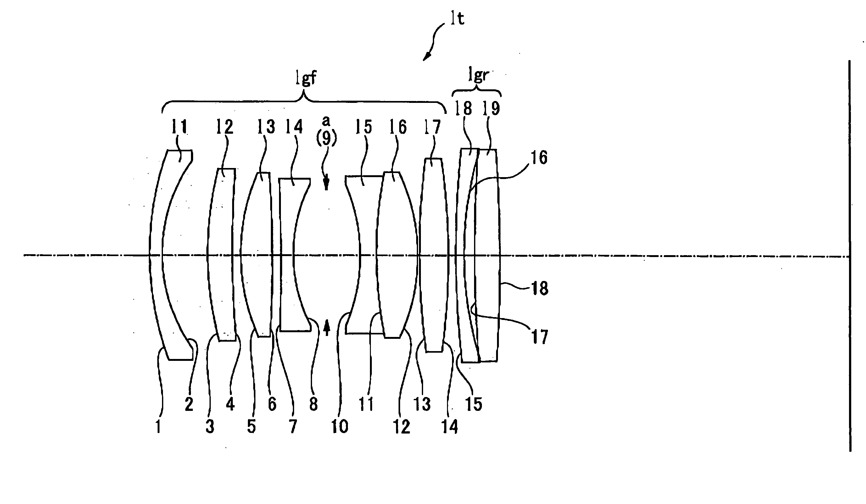
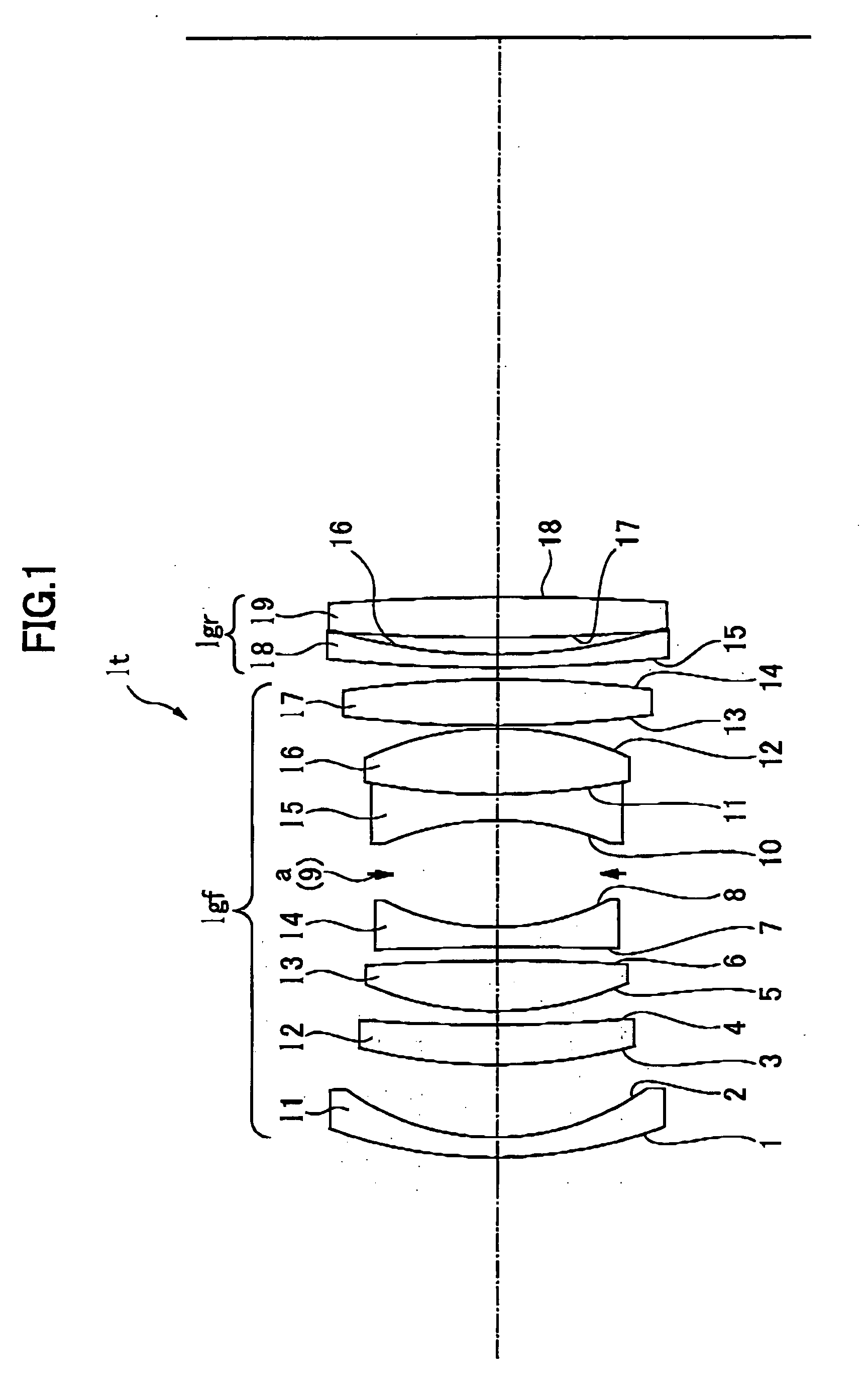
[0037] An embodiment of a macro lens according to the present invention will now be described. The macro lens, as can be seen in FIG. 1, consists of a front lens group of a retrofocus type 1gf of focal length denoted by Ff and a rear lens group 1gr of focal length denoted by Fr of which component lenses are aligned in the order from the closest to the subject.

[0038] The front lens group includes a first lens 11 of a negative meniscus lens of focal length F1 having its convex surface projecting toward the object, a second lens 12 of a positive lens having its one surface with greater curvature oriented toward the object, a third lens 13, a fourth lens 14 of a negative lens having its concave surface with greater curvature oriented toward the imaging plane, and fifth and sixth lenses 15 and 16 of a junction lens in combination of a negative lens with a positive lens. The negative lens of the fifth lens 15 has its one surface with greater curvature oriented toward the object, across a...


PUM


Abstract

A macro lens comprised of a front lens group of a retrofocus type and a rear lens group of which component lenses are aligned in the order from the closest to the subject. The front lens group includes a first lens of a negative meniscus lens having its convex surface projecting toward the object, a second lens of a positive lens having its one surface with greater curvature oriented toward the object, a third lens of a positive lens having its one surface with greater curvature oriented toward the object, a fourth lens of a negative lens having its concave surface with greater curvature oriented toward the imaging plane, fifth and sixth lenses of a junction lens in combination of a negative lens with a positive lens, the negative lens having its one surface with greater curvature oriented toward the object, across a space having an aperture stop, and a seventh lens of a positive lens having its one surface with greater curvature oriented toward the imaging plane, the rear lens group including an eighth negative lens and a ninth positive lens, the macro lens providing relations expressed as follows: 1.0<|F1| / Ft<1.3  1 4.0<|Fr| / Ft<6.0 where F1is a focal length of the first lens, Fr is the focal length of the rear lens group, and Ft is the focal length of the total optics of the.

Description

FIELD OF THE INVENTION [0001] The present invention relates to a macro lens, and more particularly, it relates to a macro lens suitable for use in a photographic camera dedicated to 35 mm film, a video camera, electronic still camera, and a broadcasting TV camera, and the like. BACKGROUND ART [0002] In general, a typical camera lens has its reference of aberration compensation placed in some infinitely far from the lens while a macro lens compensates aberration with the reference of proximity to the lens. However, such a macro lens is likely to be often used for the ordinary image pickup, and thus, the macro lens is desirably to be capable of compensating aberration, well covering the proximate distance through the infinitely far distance. For this purpose, a floating mechanism is employed where at least two of lens groups are independently moved for focusing. The macro lens provided in this manner is capable of covering a greater image pickup range including equi-magnification phot...

Claims


Application Information

Patent Timeline
IPC IPC(8): G02B13/04G02B13/24
CPCG02B13/24G02B13/04G02B15/22
Inventor ARAKAWA, AKIO
Owner TAMRON
Learn More