Over-current protection apparatus

a protection apparatus and overcurrent technology, applied in the direction of resistors emergency protection circuit arrangements for limiting excess voltage/current, etc., can solve the problems of wasting system space, generating large transient current, and too many discrete single devices, so as to increase the mechanical strength

Inactive Publication Date: 2005-06-30
POLYTRONICS TECH
View PDF14 Cites 6 Cited by
  • Summary
  • Abstract
  • Description
  • Claims
  • Application Information

AI Technical Summary

Benefits of technology

[0013] The bonding sheet is usually close to the bottoms of the over-current protection devices for the convenience of cutting. Nevertheless, if the over-current protection device comprises two current-sensitive elements, the bonding sheet can be disposed therebetween to increase the mechanical strength.

Problems solved by technology

Moreover, some components may generate large transient current due to interference.
If an over-current protection apparatus is not employed to respond to the increasing temperature, and the large current is not cut off by breaking down circuit and increasing resistance, the relevant core circuit or battery will change the nature owing to high temperature, resulting in permanent damage.
However, too many discrete single devices waste space of a system.

Method used


Image

  • Over-current protection apparatus
  • Over-current protection apparatus
  • Over-current protection apparatus

Examples


Embodiment Construction

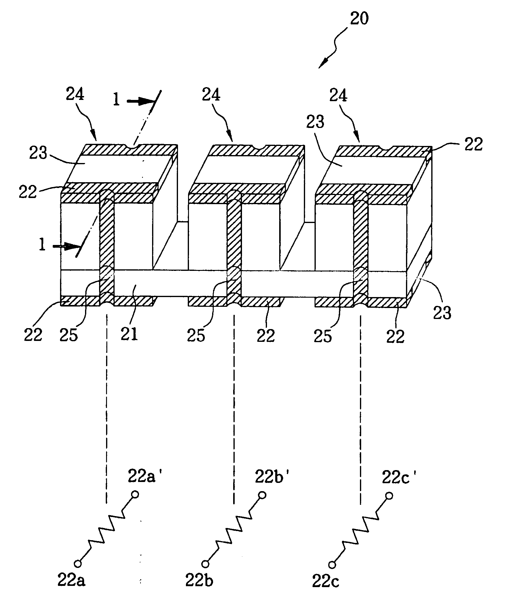
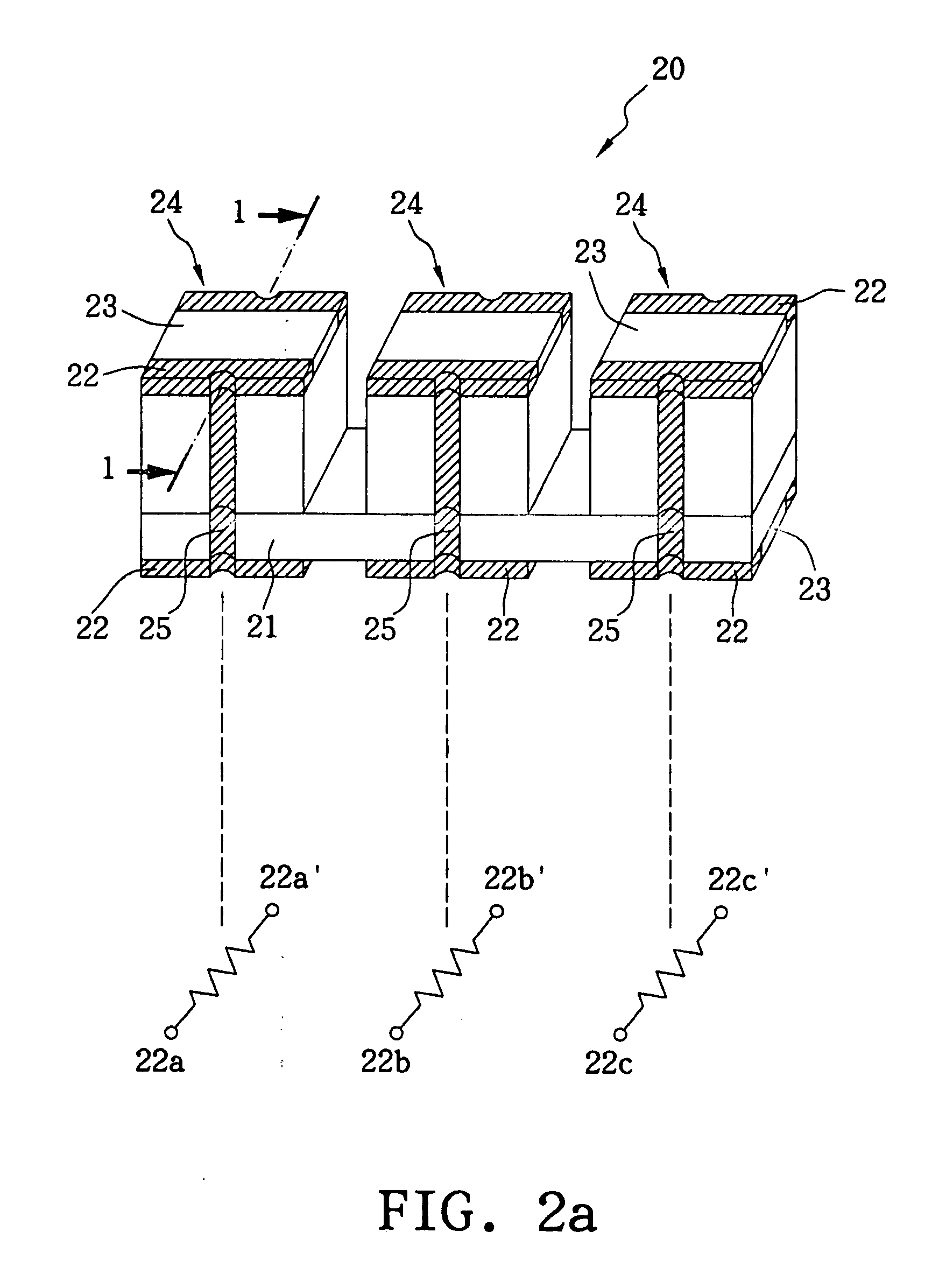
[0020]FIG. 2a illustrates an over-current protection apparatus 20 and the schematic diagram thereof. The over-current protection apparatus 20 comprises a bonding sheet 21 and a plurality of over-current protection devices 24 which are electrically independent, (three over-current protection devices 24 are employed as an example herein,) where the plurality of over-current protection devices 24 are connected in series near the bottom thereof by the bonding sheet 21. Each over-current protection device 24 has upper and lower outer electrode layers 22 serving as end electrodes and solder-mask layers 23, where a semi-cylindrical conductive hole 25 connects the upper and lower outer electrode layers 22. A schematic diagram of the over-current protection apparatus 20 is illustrated in FIG. 2a also, wherein each resistance corresponds to each over-current protection device, individually, and the end electrodes of the resistances are denoted by 22a, 22a′, 22b, 22b′, 22c and 22c′.

[0021] The...


PUM


Abstract

An over-current protection apparatus comprises a plurality of over-current protection devices and a bonding sheet. Each over-current protection device comprises at least one current-sensitive element, two outer electrode layers and at least one insulating layer disposed on a surface of the current-sensitive element. The bonding sheet penetrates and connects the plurality of over-current protection devices, and is disposed on a surface of the at least one current-sensitive element for insulation.

Description

BACKGROUND OF THE INVENTION [0001] (A) Field of the Invention [0002] The present invention is related to an over-current protection apparatus, and more specifically to an over-current protection apparatus of surface mount technology (SMT) type, which is in the form of a string or an array. [0003] (B) Description of the Related Art [0004] To prevent over-current or over-temperature from occurring in a circuitry, the current portable electronic appliances such as cellular phones, laptop computers, portable video cameras and personal digital assistants (PDAs) commonly are embedded with over-current protection apparatuses to prevent permanent damages to the internal circuitries owing to electrical surge. Therefore, an over-current protection apparatus is serially connected to the output or input end of a circuitry in need of protection, so as to prevent core circuit or battery from being damaged. [0005] Most electronic devices generate heat during operation, inducing the temperatures th...

Claims


Application Information

Patent Timeline
Patent Type & Authority Applications(United States)
IPC IPC(8): H01C7/13
CPCH01C7/13
Inventor MA, YUN CHINGYU, CHING HAN
Owner POLYTRONICS TECH
Why Eureka
Try Eureka