
Optical disc apparatus, an optical disc method, and a semiconductor integrated circuit

a technology of optical discs and semiconductors, applied in the direction of digital signal error detection/correction, instruments, recording signal processing, etc., can solve the problems of reducing the amplitude of the tracking error signal (te signal), increasing the thickness of the protection layer of the optical disc, and generating a large amount of spherical aberration, so as to achieve optimal reproduction signal quality and maintain the stability of tracking control

Active Publication Date: 2005-06-30
PANASONIC CORP
View PDF8 Cites 17 Cited by
  • Summary
  • Abstract
  • Description
  • Claims
  • Application Information

AI Technical Summary

Benefits of technology

[0025] According to the present invention, a two-dimensional first search is performed while the tracking control is in the off-state, and then a two dimensional second search is performed while the tracking control is in the on-state (two-dimensional search × two-step search). As a result, the focus position of the light beam and the spherical aberration amount can be adjusted such that the reproduced signal quality becomes optimal while maintaining the stability of the tracking control.

Problems solved by technology

However, when a numeral aperture (NA) of the light beam is increased and a wavelength of the light beam is decreased, a spherical aberration amount generated due to an error in the thickness of the protection layer of the optical disc is increased rapidly.
However, during the process for adjusting the focus position of the light beam and the spherical aberration amount, there may be a case where the amplitude of the tracking error signal (TE signal) is reduced rapidly and the tracking control becomes unstable.
According to the conventional method, during the process for adjusting the focus position of the light beam and the spherical aberration amount such that the envelop signal of the RF signal becomes maximum, there may be a case where the tracking control becomes unstable and the adjustment is terminated unsuccessfully.

Method used


Image

  • Optical disc apparatus, an optical disc method, and a semiconductor integrated circuit
  • Optical disc apparatus, an optical disc method, and a semiconductor integrated circuit
  • Optical disc apparatus, an optical disc method, and a semiconductor integrated circuit

Examples


embodiment 2

(Embodiment 2)

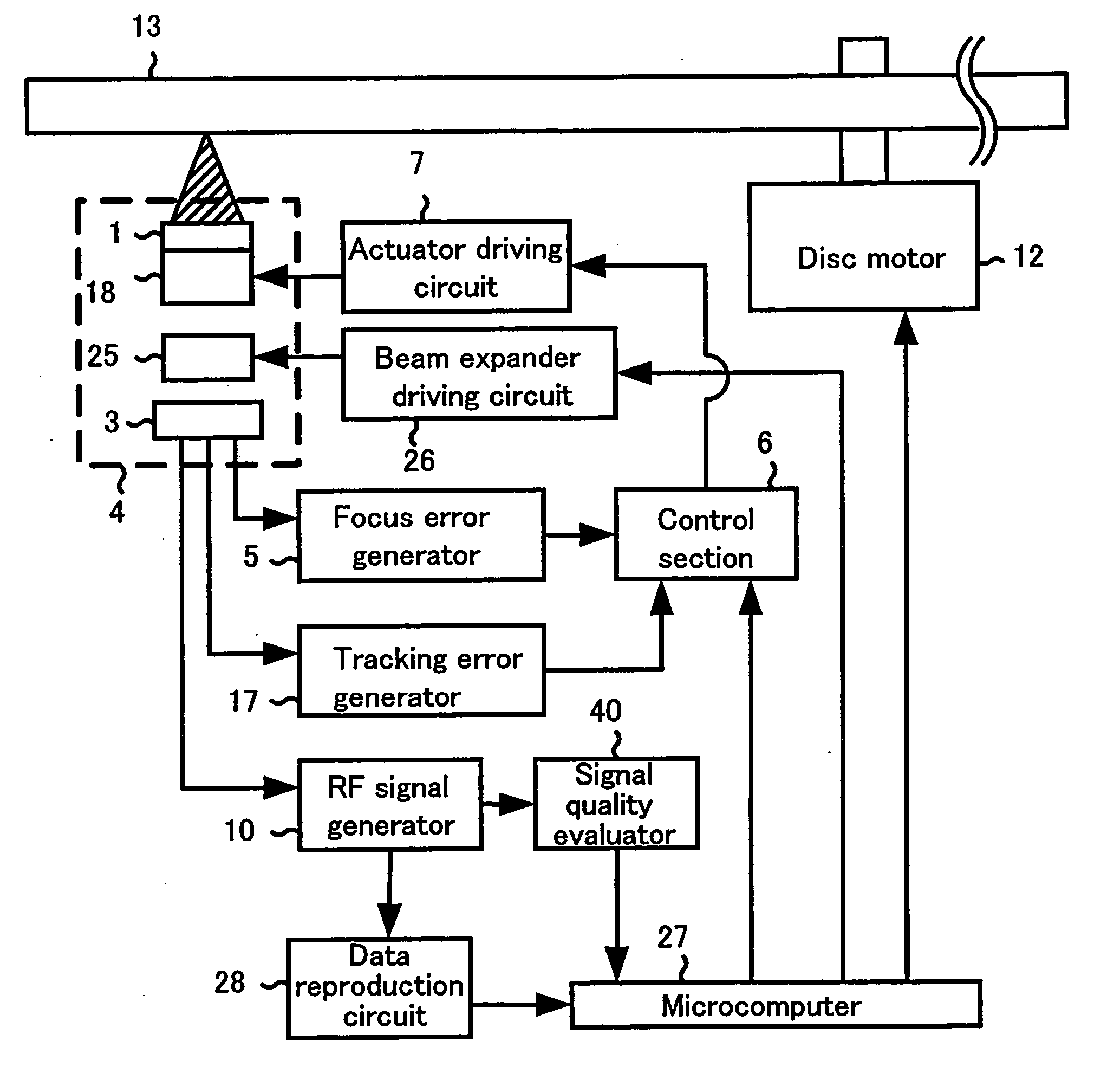
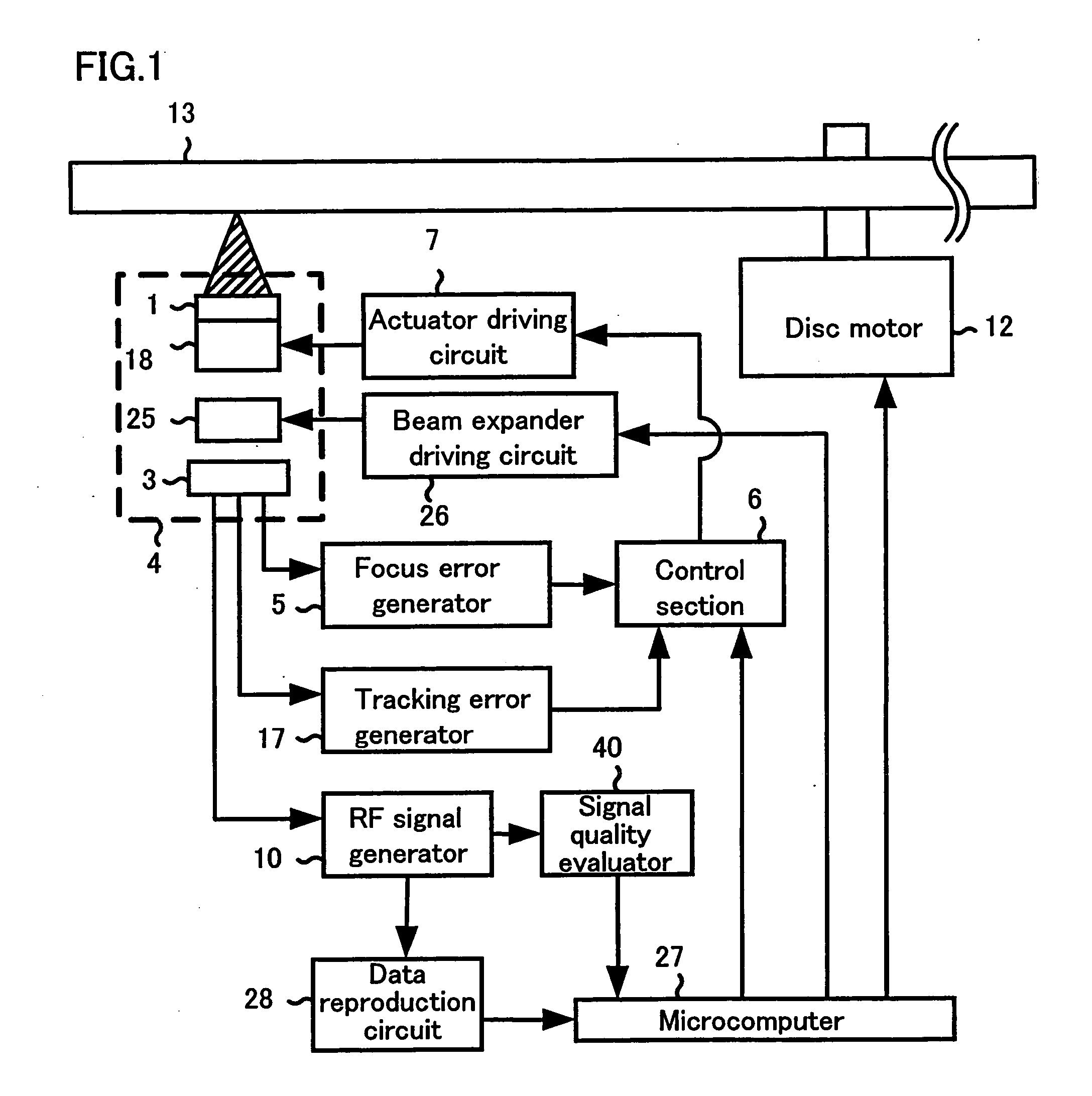
[0152] An optical disc apparatus according to embodiment 2 of the present invention has a configuration which is the same as that of the optical disc apparatus shown in FIG. 1.

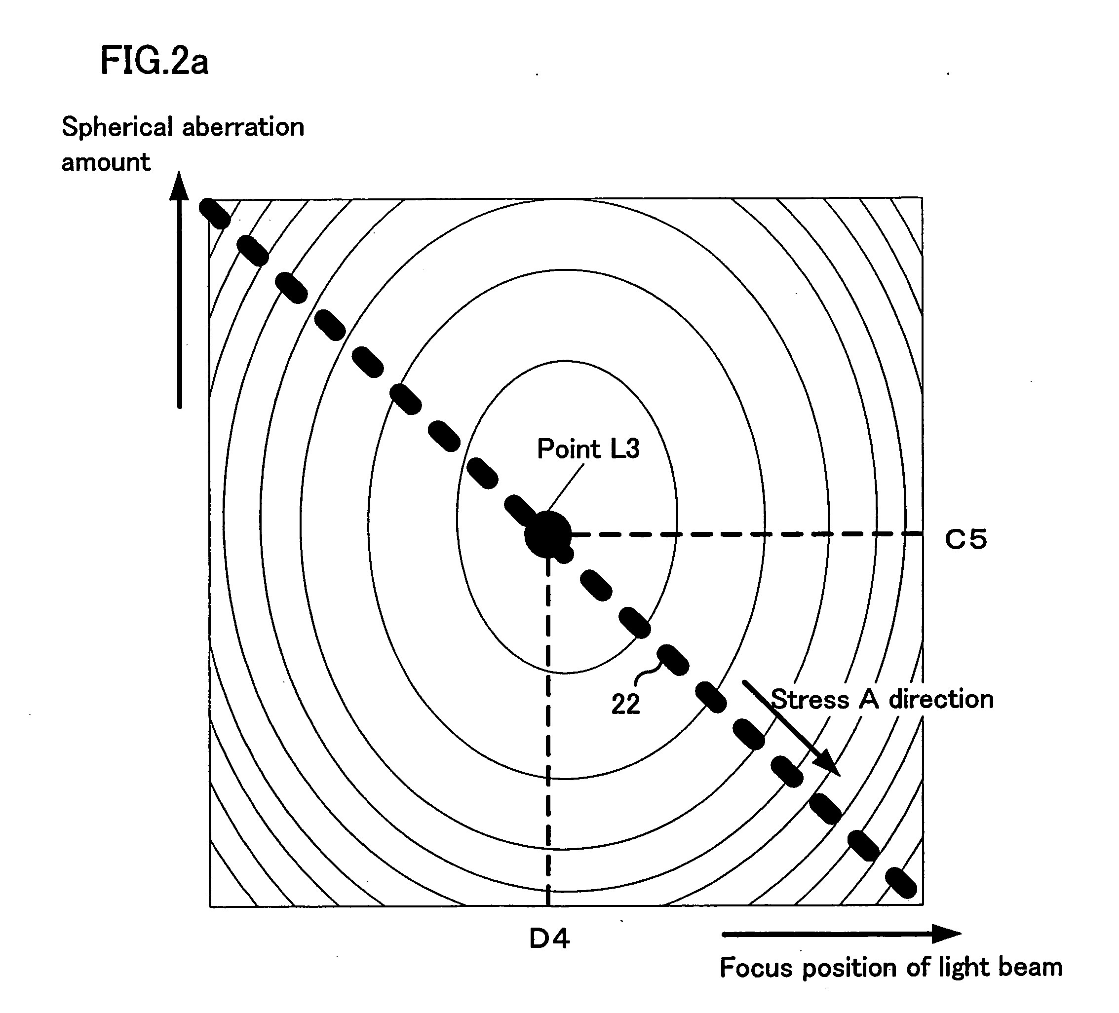
[0153] The characteristic of the MLSA signal and the amplitude characteristic of the TE signal with respect to the focus position of the light beam and the spherical aberration amount will be described below.

[0154]FIG. 2c shows the characteristic of the MLSA signal of the RF signal with respect to the focus position of the light beam and the spherical aberration amount. The lateral axis and the vertical axis shown in FIG. 2c are the same as those shown in FIG. 10. The value of the MLSA signal is represented by a contour line map including a plurality of concentric ellipses. The value of the MLSA signal on a contour line is constant. The value of the MLSA signal becomes smaller as the point on the map approaches the center of each ellipse. Accordingly, the value of the MLSA signal becomes minimu...

embodiment 3

(Embodiment 3)

[0164]FIG. 15 shows a configuration of an optical disc according to embodiment 3 of the present invention. In FIG. 5, the same reference numerals are applied to elements which are the same as those of the optical disc apparatus shown in FIG. 1, and the description of these elements are omitted herein.

[0165] A thermometer 30 measures an internal temperature of the optical pickup 4. The thermometer 30 is provided for the purpose of detecting a temperature change of a laser source (not shown) provided in the optical pickup 4. The thermometer 30 may directly detect a temperature change of the laser source by measuring the temperature of the laser source. Alternatively, the thermometer 30 may indirectly detect a temperature change of the laser source by placing the thermometer 30 at a position which is separate from the laser source within the optical pickup 4 and measuring the temperature of the internal temperature of the optical pickup 4.

[0166]FIG. 17 shows a structure...


PUM

PropertyMeasurementUnit
thicknessaaaaaaaaaa
areaaaaaaaaaaa
temperatureaaaaaaaaaa

Abstract

An optical disc apparatus includes a control section. The control section performs a first search while the tracking control is in the off state. The first search is for searching for a plurality of sets of the focus positions of the light beam and the spherical aberration amounts such that an amplitude of the tracking error signal is greater than a predetermined value. The control section performs a second search while the tracking control is in the on state. The second search is for determining a set of the focus position of the light beam and the spherical aberration amount such that the reproduced signal quality index is substantially optimal, among the plurality of sets of the focus positions of the light beam and the spherical aberration amounts obtained in the first search.

Description

BACKGROUND OF THE INVENTION [0001] 1. Field of the Invention [0002] The present invention relates to an optical disc apparatus, an optical disc method and a semiconductor integrated circuit capable of performing a recording or reproduction at a high density for an optical disc by accurately adjusting a focus position of a light beam and a spherical aberration amount. [0003] 2. Description of the Related Art [0004] As a method for increasing the recording density for an optical disc, a method for reducing the size of a spot of a light beam formed on an information surface of the optical disc is known. The reduction of the size of the spot of the light beam formed on the information surface of the optical disc is achieved by increasing a numeral aperture (NA) of the light beam and decreasing a wavelength of the light beam. [0005] However, when a numeral aperture (NA) of the light beam is increased and a wavelength of the light beam is decreased, a spherical aberration amount generated...

Claims


Application Information

Patent Timeline
Patent Type & Authority Applications(United States)
IPC IPC(8): G11B7/00G11B7/004G11B7/085G11B7/09G11B7/135G11B7/1392
CPCG11B7/0908G11B7/13925G11B7/0945G11B7/09G11B7/126
Inventor SHIMAMOTO, TAKESHIYAMADA, SHIN-ICHIKADOWAKI, SHIN-ICHIKUZE, YUUICHIKONDO, KENJIWATANABE, KATSUYA
Owner PANASONIC CORP
Learn More