Eureka AIR delivers breakthrough ideas for toughest innovation challenges, trusted by R&D personnel around the world.

Operating a rotatable media storage device at multiple spin-speeds

a technology of rotatable media and storage devices, which is applied in the direction of digital signal error detection/correction, instruments, recording signal processing, etc., can solve the problems of head damage, data damage permanent, and damage to both disk surfaces and heads

Inactive Publication Date: 2005-06-30
PANASONIC CORP
View PDF22 Cites 23 Cited by
  • Summary
  • Abstract
  • Description
  • Claims
  • Application Information

AI Technical Summary

Benefits of technology

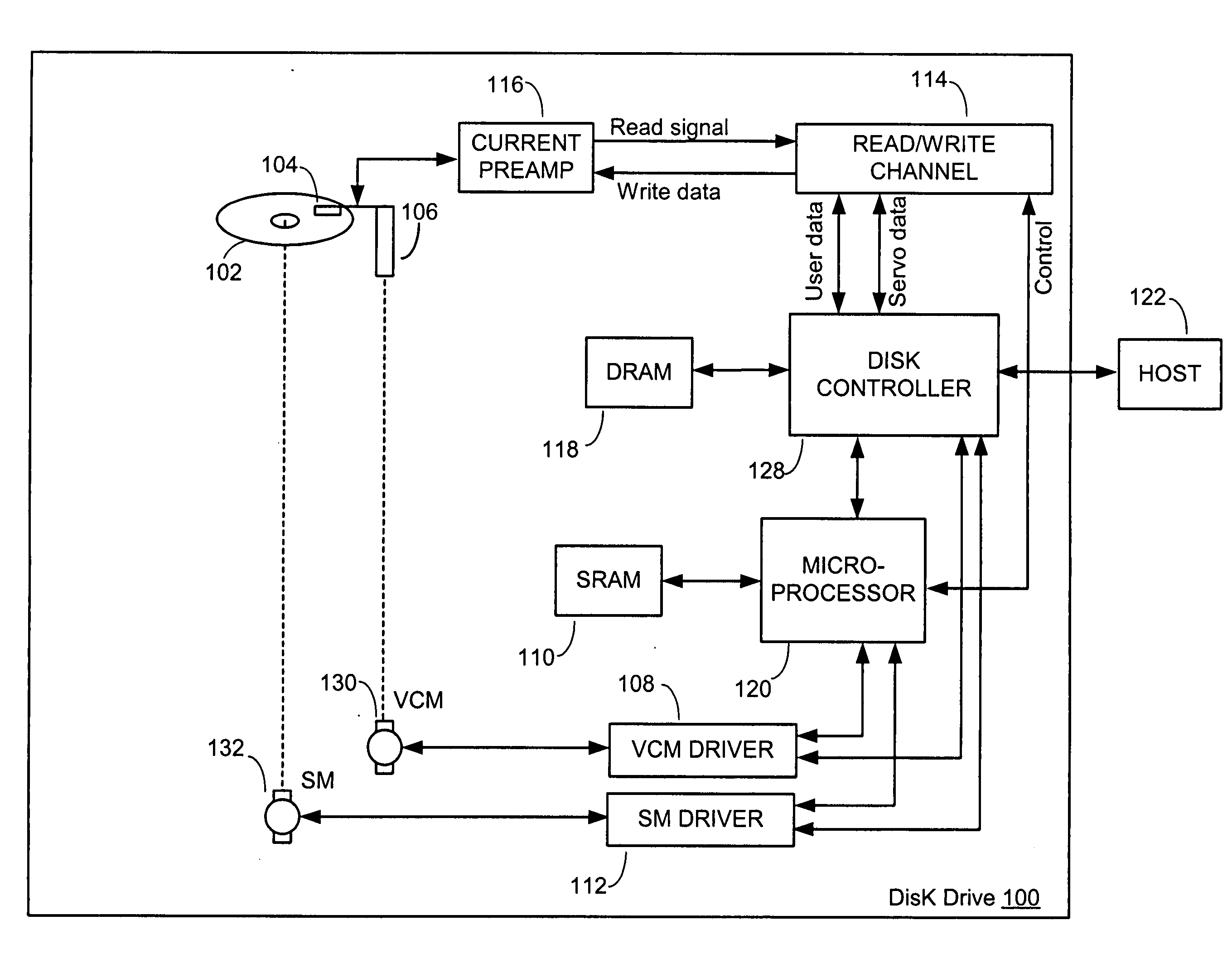
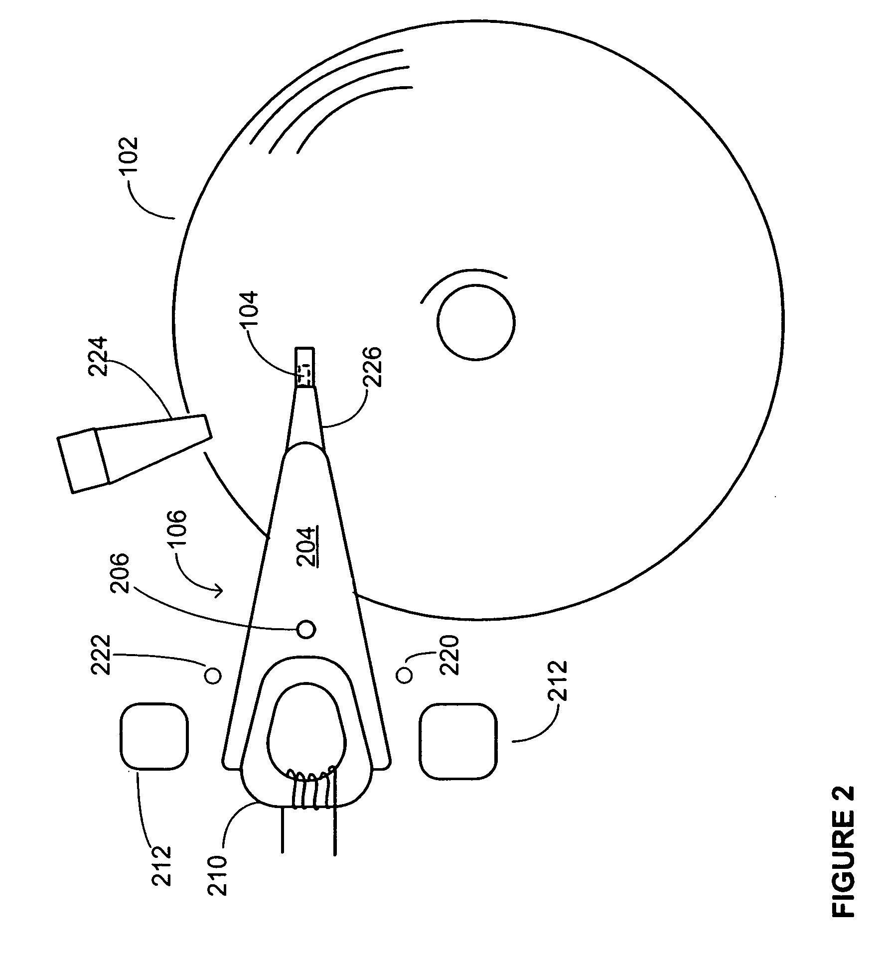
[0044] It is also possible, in accordance with an embodiment of the present invention, that the drive can use measures of back EMF to get the heads close to a desired track on the disk (for reading or writing), even before the disk reaches a spin-speed at which the drive can begin servoing (e.g., the nominal spin-speed). For example, if the drive knows that the first track to read from or write to is near the inner diameter of the disk, then the drive can use measures of back EMF to guide the head toward a location near the inner diameter of the disk such that once the disk reaches a desired spin-speed (e.g., the nominal spin-speed) at which it can begin servoing, there is less distance that the actuator arm will need to travel in order to place head over the desired track.

Problems solved by technology

It is preferred that the head and disk surface not come in contact while the disk is rotating, since this can result in damage to both the disk surface and the head.
For example, data can be permanently destroyed if excessive contact should occur.
Also, the head can be damaged by the contact.
This is because the head and disk surface may stick together, if the disk and the head are at rest and in contact for a period of time, resulting in damage to the disk surface and / or head when the disk starts to rotate.
Also, since the disk starts spinning from rest, and a certain minimum velocity is required for the head to float over the disk surface, each startup of the hard drive can result in the head and disk surface rubbing for a distance until the disk achieves sufficient speed to form the aforementioned air cushion.
The rotation of disks, within rotatable storage drives of portable computing devices, consumes power from the batteries.

Method used


Image

  • Operating a rotatable media storage device at multiple spin-speeds
  • Operating a rotatable media storage device at multiple spin-speeds
  • Operating a rotatable media storage device at multiple spin-speeds

Examples


Embodiment Construction

[0022] Embodiments of the present invention are useful for reducing the amount of time it takes for a head to begin reading from and / or writing to a disk, after an actuator assembly has been parked on a load / unload ramp and the disk has not been rotating. In accordance with an embodiment of the present invention, a disk spin-speed is monitored as a disk spins up from rest. The disk may have been at rest, for example, because the drive had just been powered on, or because the drive had been in a power saving (e.g., idle) mode. In accordance with an embodiment of the present invention, the drives “time-to-ready” is reduced by beginning a ramp load operation before the disk spin-speed reaches its nominal spin-speed, and in accordance with specific embodiments, even before the disk spin-speed achieves a minimum float spin-speed for causing the head to float over a surface of the disk. However, before explaining further details and embodiments of the present invention, it is first useful...


PUM


Abstract

A rotatable media storage device operates using multiple disk spin-speeds, e.g., a reduced spin-speed and a nominal spin-speed. A disk is spun up to a reduced spin-speed and an initial data transfer is began while the disk spins at the reduced spin-speed, if an amount of work that has been requested is below a threshold. The disk is spun up to a further spin-speed (e.g., a nominal spin-speed), which is greater than the reduced spin-speed, and the initial data transfer is began while the disk spins at the further spin-speed, if the amount of work that has been requested is above the threshold. Alternative embodiments using multiple disk spin-speeds are also provided.

Description

CLAIM OF PRIORITY [0001] This application claims priority under 35 U.S.C. 119(e) to U.S. Provisional Patent Application No. 60 / 530,504, filed Dec. 18, 2003, and entitled “Operating A Rotatable Media Storage Device At Multiple Spin-Speeds.”[0002] This application also claims priority under 35 U.S.C. 119(e) to U.S. Provisional Patent Application No. 60 / 530,491, filed Dec. 18, 2003, and entitled “Reducing the Time-To-Ready in a Rotatable Media Storage Device.”[0003] This application is also a continuation-in-part of U.S. patent application Ser. No. 10 / 366,237, filed Feb. 13, 2003, and entitled “Intermediate Power Down Mode for a Rotatable Media Data Storage Device,” which claims priority under 35 U.S.C. 119(e) to U.S. Provisional Patent Application No. 60 / 436,946, entitled “Intermediate Power Down Mode for a Rotatable Media Data Storage Device,” filed Dec. 30, 2002. [0004] Each of the above applications is incorporated herein by reference.FIELD OF THE INVENTION [0005] The present inven...

Claims


Application Information

Patent Timeline
IPC IPC(8): G11BG11B5/09G11B7/00G11B19/02G11B19/26
CPCG11B19/02G11B5/09G11B19/26Y02D10/00
Inventor EHRLICH, RICHARD M.SCHMIDT, THORSTENTANNER, BRIAN K.
Owner PANASONIC CORP
Why Eureka
Eureka Blog
Learn More