Solid-phase nano extraction device

Inactive Publication Date: 2005-06-30
IND TECH RES INST
View PDF18 Cites 9 Cited by
  • Summary
  • Abstract
  • Description
  • Claims
  • Application Information

AI Technical Summary

Benefits of technology

[0006] In view of the foregoing, the disclosed SPNE device can

Problems solved by technology

However, these methods have different kinds of defects, such as high costs, complicated op

Method used


Image

  • Solid-phase nano extraction device
  • Solid-phase nano extraction device
  • Solid-phase nano extraction device

Examples


Embodiment Construction

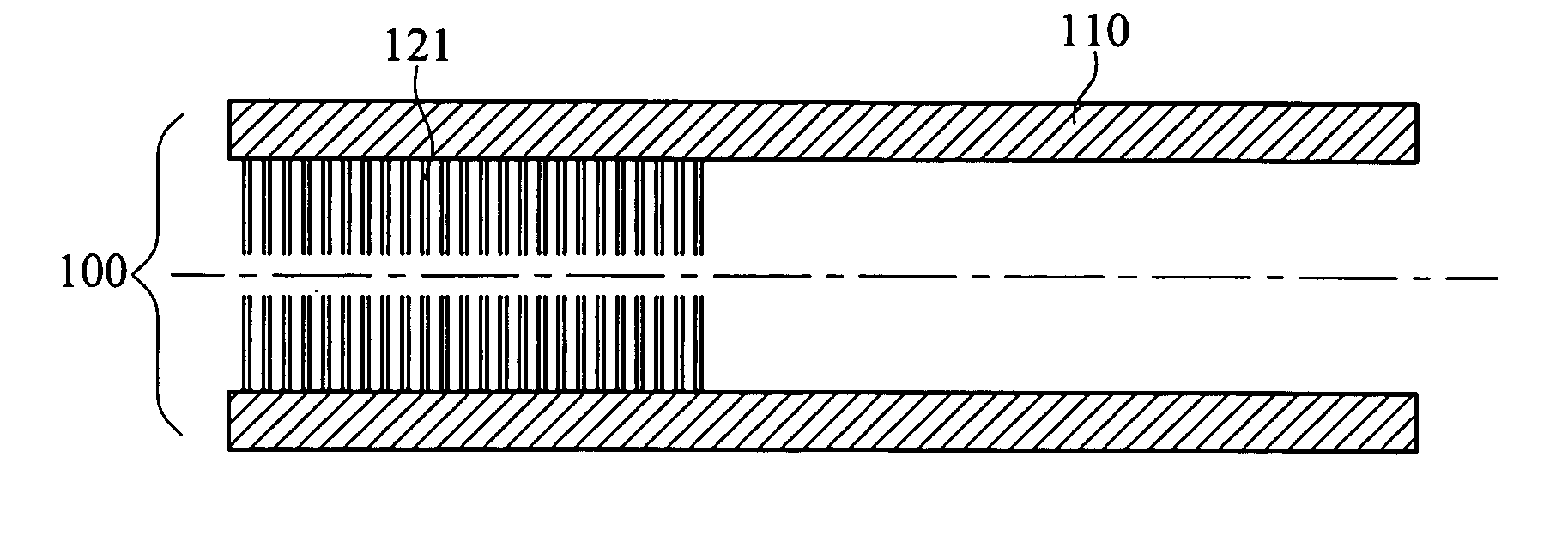
[0018] The disclosed SPME device is featured in the use of an extraction tube as the fiber. Its inner surface has a large area of nanostructure to increase the contact are between the nanostructure and the sample. Therefore, the nanostructure can adsorb samples within an extremely short reaction time.

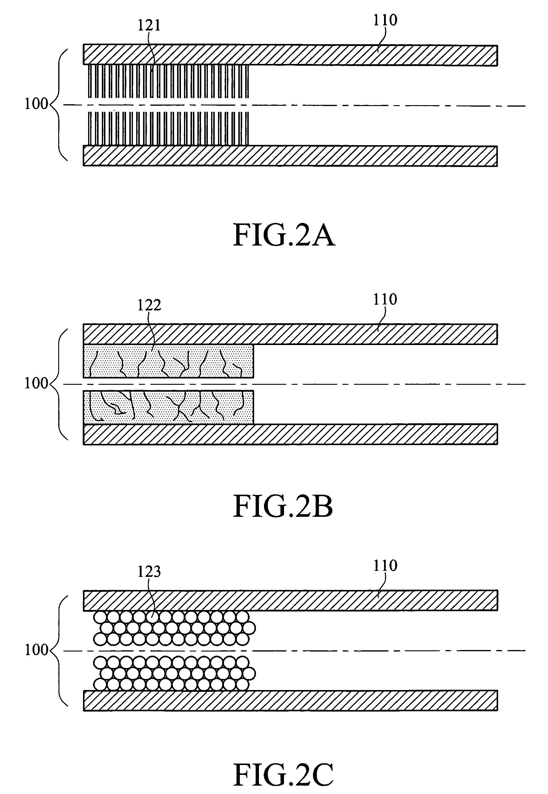
[0019] The nanostructure on the inner surface of the extraction tube can be nanotubes / fibers, a nano-porous thin film, or layered nanospheres. Various embodiments of the extraction tube are shown in FIGS. 2A to 2C. As shown in FIG. 2A, the extraction tube 100 is a hollow stainless tube 110, whose inner surface is formed with a hollow carbon nanotube array 121. Since the carbon nanotube has a hollow structure, it has a high BET surface area to adsorb samples. The diameter of the carbon nanotube can be micro-porous, meso-porous, and macro-porous ranging from 1 nm to 500 nm, as defined by the International Union of Pure and Applied Chemistry (IUPAC). The hollow nature of the carbon nanotu...


PUM

PropertyMeasurementUnit
Sizeaaaaaaaaaa
Sizeaaaaaaaaaa
Forceaaaaaaaaaa

Abstract

A solid-phase nano extraction device includes an extraction tube whose inner surface has a nanostructure for a large contact area with object to be detected. The nanostructure can adsorb objects in an extremely short reaction time. A driving structure is designed for the solid-phase micro extraction device. The extraction tube is connected to the driving structure for the objects to enter the fiber under the force of concentration gradient, pressure difference, or capillary force, thereby being adsorbed onto the nanostructure.

Description

BACKGROUND OF THE INVENTION [0001] 1. Field of Invention [0002] The invention relates to an extraction device and, in particular, to a solid-phase micro extraction device. [0003] 2. Related Art [0004] When analyzing organic components of a complex sample, one often uses such techniques as liquid-liquid extraction, solid-phase extraction (SPE), and super-phase extraction (SFE). However, these methods have different kinds of defects, such as high costs, complicated operations, long operation time, or pollution of organic solvents poisonous to human bodies. The traditional solid-phase micro extraction (SPME) developed according to the SPE has the advantages of a shorter sample processing time in the sample pretreatment, simpler operation steps, reduced organic solvent uses, and reduced loss of analyzed materials. [0005] This invention develops a novel solid-phase nano extraction (SPNE) device that overcomes defects in conventional sample pretreatment technology. It does not need any so...

Claims


Application Information

Patent Timeline
IPC IPC(8): B01L99/00B01L3/00B01L3/02G01N1/40
CPCB01J20/205B01J20/28007B01J20/28019B01L3/0217B01L3/0275Y10T436/25375B01L2300/0838B01L2300/0896B82Y30/00G01N1/40G01N1/405B01L2200/0631
Inventor CHEN, JIN-MINGHSIEH, CHIEN-TEHUANG, YUE-HAOKUO, RONG-RONGLIN, YU-RUNHU, CHIUNG-WENCHAO, MU-RONGWU, KUEN-YUH
Owner IND TECH RES INST
Why Eureka
Try Eureka