

Magnetic recording medium
a recording medium and extremely fine structure technology, applied in the field of magnetic recording mediums, can solve the problems that the magnetic recording medium having such a fine structure cannot have a high signal-to-noise ratio and the grain size has been reduced, and achieve the effect of suppressing the formation of narrow grain boundaries, reducing the noise of the medium, and high signal-to-noise ratio
- Summary
- Abstract
- Description
- Claims
- Application Information
AI Technical Summary
Benefits of technology
Problems solved by technology
Method used
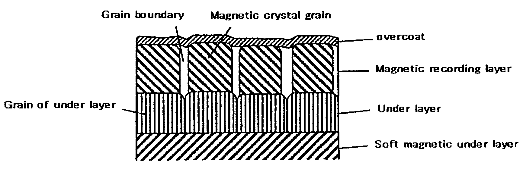
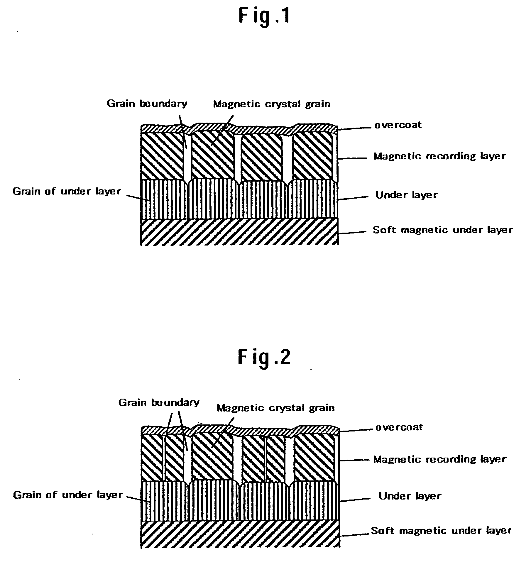
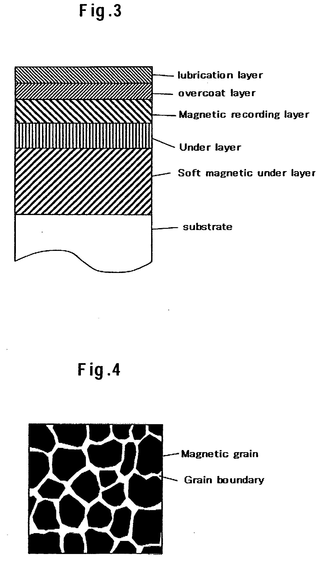
Image

Examples
experimental example 1
[0034] In a first magnetic recording medium according to Experimental Example 1, an NiTa37.5Zr10 film was formed first on a chemically reinforced glass substrate through alkaline cleaning to a thickness to 30 nm. Here, the number 37.5 after Ta and the number 10 after Zr in NiTa37.5Zr10 represent the respective concentrations of Ta and Zr contained in the film in atomic percentage. In short, NiTa37.5Zr10 is an abbreviated representation of 52.5 at.% Ni-37.5at.% Ta-10at.% Zr. By contrast, a representation with no numeric value such as NiTaZr is an abbreviated representation of the same composition ratio as that of a film containing the same elements and shown immediately before. Similar abbreviated representations will be used herein below. Then, a FeCo30B15 film was formed to a thickness to 300 nm and a Ta film was formed to a thickness of 1 nm. Thereafter, an Ru film was formed under the condition that the pressure of an Ar gas was 2.0 Pa by a DC magnetron sputtering process. At thi...
experimental example 2
[0042] In a magnetic recording medium according to Experimental Example 2, NiTa37.5 was deposited on a crystallized glass substrate through alkaline cleaning at a room temperature and a soft magnetic underlayer was formed by repeating the stacking of a FeTa10C12 layer with a thickness of 100 nm and a Ta layer with a thickness of 1.0 nm in three cycles. Thereafter, the surface of the soft magnetic underlayer was heated to 350° C. by using an infrared lamp and then cooled to a room temperature. Then, an underlayer, a magnetic recording layer, and an overcoat layer were formed. As the underlayer, Ru was formed to a film thickness of 10 nm. The magnetic recording layer was formed to have a film thickness of 15 nm such that the volume ratio between CoCr19Pt14 and SiO2 became 75:25. The pressure of an Ar sputter gas when the magnetic recording layer was formed was adjusted to 4.0 Pa and an amount of oxygen contained in the sputter gas was adjusted to 0.5%. As the overcoat layer, C was dep...
PUM
| Property | Measurement | Unit |
|---|---|---|
| thickness | aaaaa | aaaaa |
| thickness | aaaaa | aaaaa |
| size | aaaaa | aaaaa |
Abstract
Description
Claims
Application Information