Cold-molding process for loading a stent onto a stent delivery system

a stent and stent technology, applied in the field of cold molding process for loading a stent onto a stent delivery system, can solve the problems of less than optimal securement of the stent to the balloon, premature dislodgment of the stent, and difficulty in maintaining the stent on the balloon and in achieving symmetrical expansion of the stent, so as to improve the positional stability of the stent during the delivery.

Active Publication Date: 2005-06-30
ABBOTT LAB VASCULAR ENTERPRISE
View PDF102 Cites 61 Cited by
  • Summary
  • Abstract
  • Description
  • Claims
  • Application Information

AI Technical Summary

Benefits of technology

[0018] It is an object to provide methods and apparatus for loading a stent onto a stent delivery system that enhance positional stability of the stent during delivery.
[0019] It is an object to provide methods and apparatus for loading a stent onto a stent delivery system wherein the delivery system comprises a crossing profile and flexibility suitable for use in tortuous and narrowed anatomy.
[0020] It is also an object to provide methods and apparatus for loading a stent onto a stent delivery system that provide a substantially symmetrical expansion of the stent at deployment.
[0024] Optionally, pillows or bumpers may be formed in the proximal and / or distal regions of the balloon during crimping that, in conjunction with the non-uniform creases of the balloon, prevent longitudinal movement of the stent with respect to the balloon during intravascular delivery.

Problems solved by technology

Significant difficulties have been encountered during stent delivery and deployment, including difficulty in maintaining the stent on the balloon and in achieving symmetrical expansion of the stent when deployed.
Such techniques have several drawbacks, including less than optimal securement of the stent to the balloon.
Consequently, the stent may become prematurely dislodged from the balloon during advancement of the stent delivery system to the treatment site.
However, the exterior sheath increases the crossing profile of the delivery system while decreasing flexibility, thereby decreasing the ability of the device to track through narrowed and tortuous anatomy.
As with the removable sheaths discussed previously, the stoppers are expected to increase delivery profile and decrease flexibility of the stent / balloon system.
A drawback to this device is the added complexity involved in manufacturing a balloon with pre-formed protrusions.
Additionally, if the protrusions are not formed integrally with the balloon, there is a risk that one or more of the protrusions may detach during deployment of the stent.
The protrusions may also reduce flexibility in the delivery configuration, thereby reducing ability to track through tortuous anatomy.
A significant drawback of Jendersee's encapsulation method is the need to heat the balloon in order to achieve encapsulation.
Such heating while under pressure may lead to localized plastic flows resulting in inhomogeneities along the length of the balloon including, for example, varying wall thickness.
Varying wall thickness may, in turn, yield areas of decreased strength that are susceptible to rupture upon inflation of the balloon during deployment of the stent.
Additionally, heating and cooling increases the complexity, time, and cost associated with affixing the stent to the balloon.
Chemically softening the balloon material under pressure is expected to introduce inhomogeneities along the length of the balloon, such as varying wall thickness, which again may lead to failure of the balloon.
Additionally, chemical alteration of the balloon, via application of a solvent to the surface of the balloon, may unpredictably degrade the mechanical characteristics of the balloon, thereby making accurate and controlled deployment of a stent difficult.
Softening also adds cost, complexity, and time to the manufacturing process.

Method used


Image

  • Cold-molding process for loading a stent onto a stent delivery system
  • Cold-molding process for loading a stent onto a stent delivery system
  • Cold-molding process for loading a stent onto a stent delivery system

Examples


Embodiment Construction

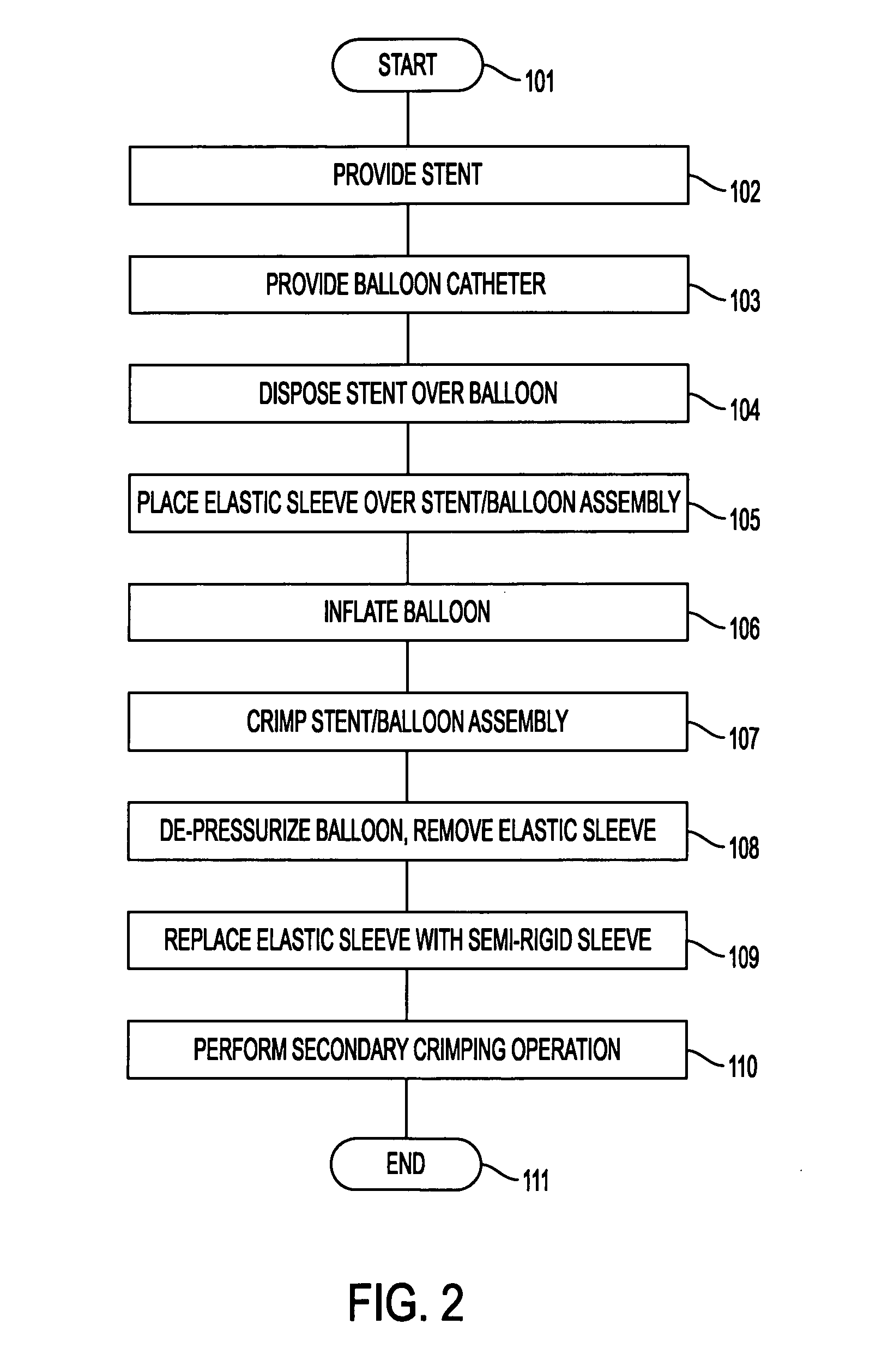
[0037] The present invention comprises methods and apparatus for cold-molding a stent onto a stent delivery system. More specifically, the present invention provides methods and apparatus for obtaining a balloon having creases that extend non-uniformly into the interstices of a stent loaded onto the exterior of the balloon, without the use of a heating or chemical process.

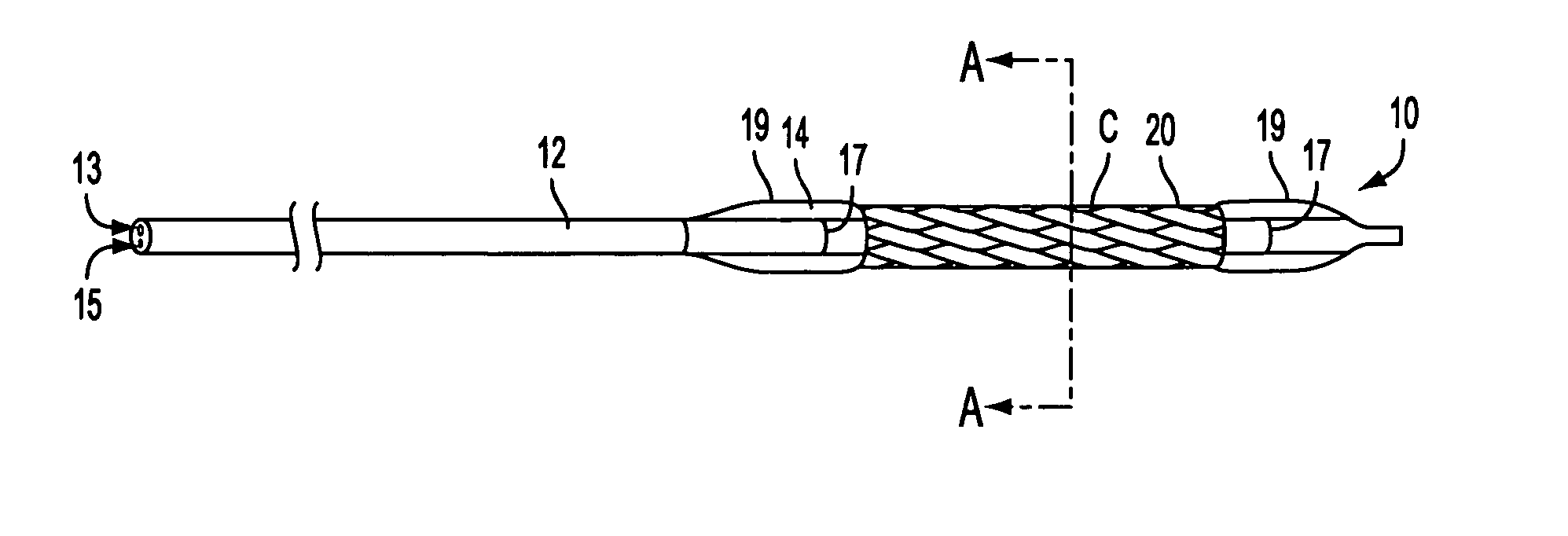
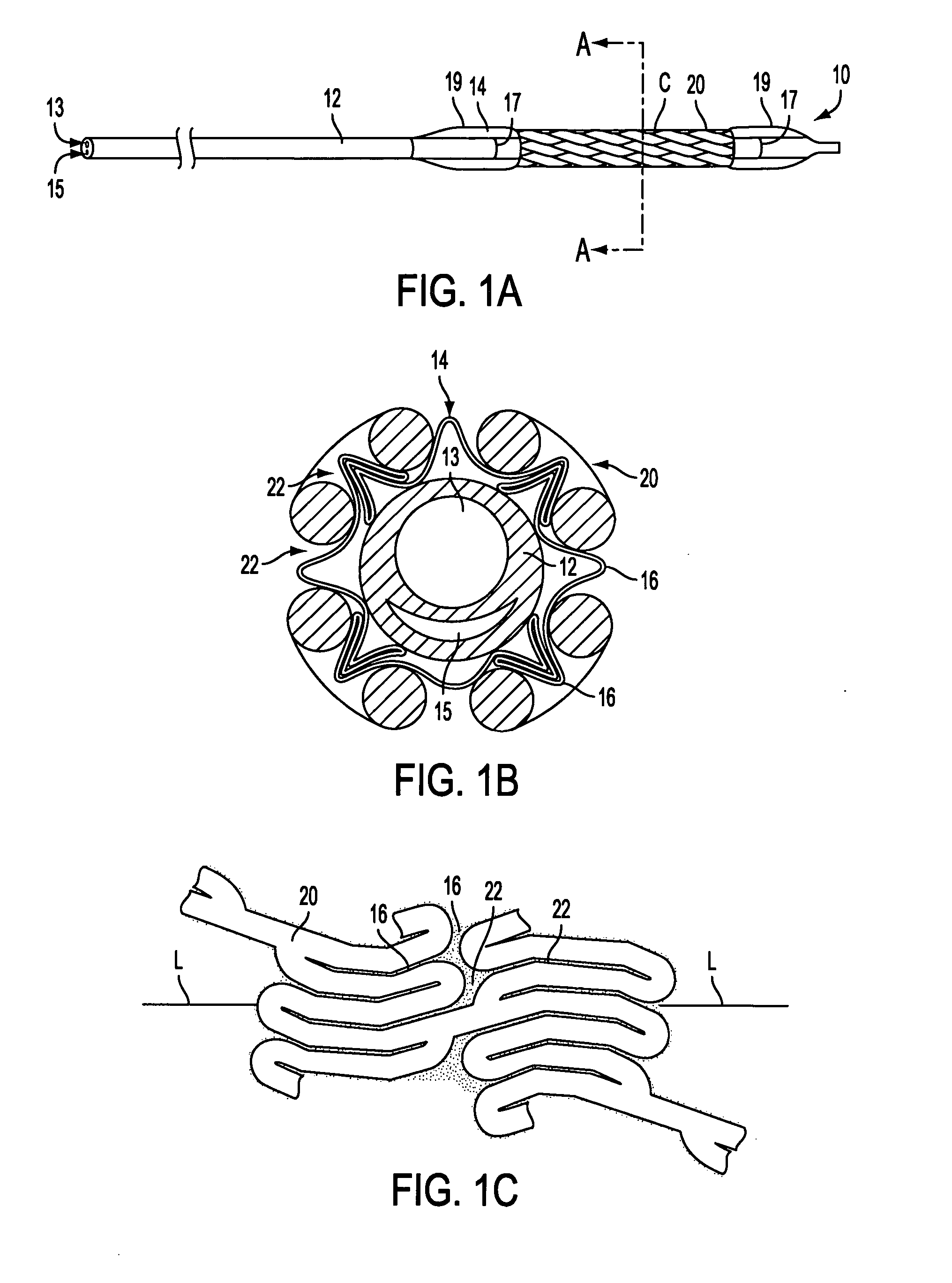
[0038] With reference to FIGS. 1, apparatus in accordance with the present invention is described. As seen in FIG. 1A, stent delivery system 10, illustratively shown in a collapsed delivery configuration, comprises balloon expandable stent 20 loaded on balloon 14 of delivery catheter 12. Stent 20 comprises an illustrative balloon expandable stent and may be replaced with other stents known in the art. As seen in FIGS. 1B and 1C, balloon 14 has creases 16 that extend non-uniformly into interstices 22 of stent 20.

[0039] In FIG. 1B, creases 16 are shown with varying slope and height about the circumference of stent ...


PUM

PropertyMeasurementUnit
pressureaaaaaaaaaa
pressureaaaaaaaaaa
pressureaaaaaaaaaa

Abstract

A method of making a stent delivery system is provided in which a delivery catheter has a balloon that extends non-uniformly into interstices of a stent. In accordance with the method a balloon / stent / crimping tube assembly is placed in a crimping tool, the balloon is inflated, and the crimping tool is actuated to compress the stent on the outside of the balloon without application of heat or chemicals, thereby causing creases of the balloon to extend non-uniformly into the interstices of the stent. Optionally, pillows may be formed in the balloon to prevent longitudinal movement of the stent with respect to the balloon during intravascular delivery. One or more secondary crimpings also may be performed to achieve a smoother delivery profile.

Description

FIELD OF THE INVENTION [0001] The present invention relates to a cold-molding process for loading a stent onto a stent delivery system. More specifically, the present invention relates to a method of loading a stent onto a balloon having creases that extend non-uniformly into the interstices of the stent without the use of a heating step. BACKGROUND OF THE INVENTION [0002] A stent is commonly used alone or in conjunction with angioplasty to ensure patency through a patient's stenosed vessel. Stents overcome the natural tendency of the vessel walls of some patients to restenose after angioplasty. A stent is typically inserted into a vessel, positioned across a lesion, and then expanded to create or maintain a passageway through the vessel, thereby restoring near-normal blood flow through the vessel. [0003] A variety of stents are known in the art, including self-expandable and expandable stents, as well as wire braid stents. One such stent is described, for example, in U.S. Pat. No. ...

Claims


Application Information

Patent Timeline
Patent Type & Authority Applications(United States)
IPC IPC(8): A61F2/06A61F2/90
CPCA61F2/91A61F2/915A61F2002/91533A61F2002/91558A61F2002/9583A61F2310/00011A61F2/9522Y10T29/49927A61F2/958A61M2025/1004
Inventor SCHWAGER, MICHAELFREI, MARTINHA, SUK-WOO
Owner ABBOTT LAB VASCULAR ENTERPRISE
Why Eureka
Try Eureka