Gear part with lubrication coating and method of manufacturing the same

a technology of lubrication coating and gear parts, which is applied in the field of gear parts, can solve the problems of increasing the manufacturing cost of the gear part, and achieve the effects of reducing the treatment temperature, increasing the manufacturing cost of the gear part, and easy formation of lubrication coatings

Inactive Publication Date: 2005-07-07
NISSAN MOTOR CO LTD
View PDF5 Cites 6 Cited by
  • Summary
  • Abstract
  • Description
  • Claims
  • Application Information

AI Technical Summary

Benefits of technology

[0005] However, to form the coating on a sliding surface of the gear part by means of chemical conversion, the gear part needs to be held in a chemical conversion solution at high temperature for a certain period of time. For example, the gear part is required to be immersed in the chemical conversion solution at a temperature as high as about 50° C. to 100° C. for about 5 to 20 minutes. As described in the Japanese Patent Application Laid-Open No. H7-90611, use of an aqueous-based chemical conversion solution can lower the treatment temperature. However, chemical conversion of the sliding surface of the gear part with a predetermined chemical conversion solution requires particular equipment, thus increasing manufacturing costs of the gear part. Therefore, a method of readily forming a lubrication coating is required.
[0007] An object of the present invention is to provide a gear part including a lubrication coating with a long-lasting lubricity and to provide a method of readily manufacturing the lubrication coating.

Problems solved by technology

However, chemical conversion of the sliding surface of the gear part with a predetermined chemical conversion solution requires particular equipment, thus increasing manufacturing costs of the gear part.

Method used


Image

  • Gear part with lubrication coating and method of manufacturing the same
  • Gear part with lubrication coating and method of manufacturing the same
  • Gear part with lubrication coating and method of manufacturing the same

Examples


examples 1 to 5

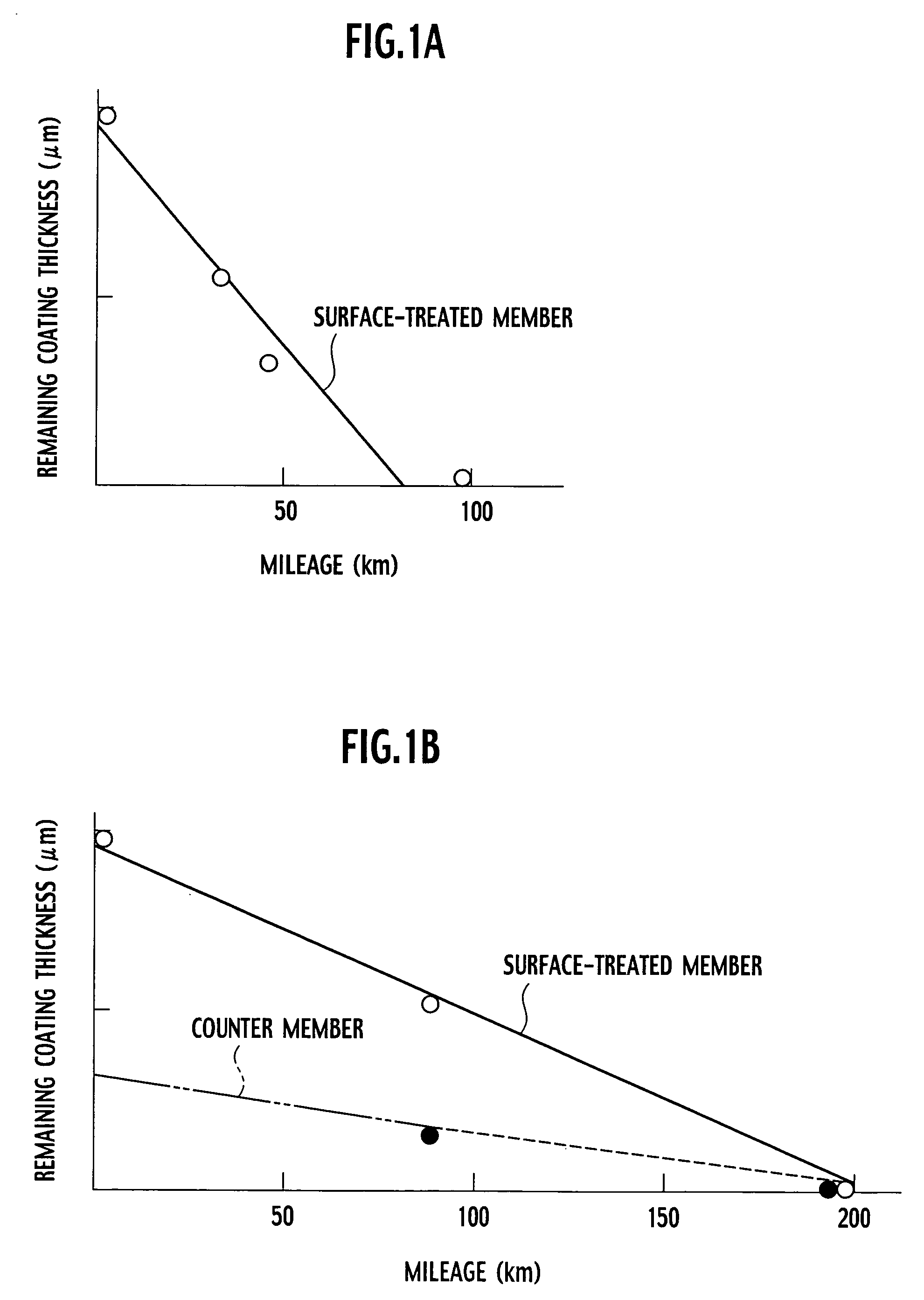
[0063] The lubricant compositions were prepared by mixing ingredients shown in FIG. 5. Gears of a final drive, which were the gear parts, are immersed in these lubricant compositions to adhere the lubricant compositions on the surfaces of the gears. Subsequently, water within the lubricant compositions was evaporated at room temperature to manufacture gears each of which had a lubrication coating formed on the surface. For checking the persistence of the lubricity, the relationship between the mileage and the remaining coating thickness was examined. In each case, it was confirmed that the lubrication coating was transferred to the counter member and the remaining coating was maintained for long periods.


PUM

PropertyMeasurementUnit
temperatureaaaaaaaaaa
thicknessaaaaaaaaaa
massaaaaaaaaaa

Abstract

A gear part of the present invention includes a lubrication coating formed on a surface of the gear part, the lubrication coating containing an organic phosphorous compound. In the gear part, when a tooth surface of the gear part is engaged with a tooth surface of a counter member, the organic phosphorous compound is transferred to the tooth surface of the counter member and another lubrication coating containing the organic phosphorous compound is formed on the tooth surface of the counter member. As a result, the lubrication coating can be held on the surface of the gear part for long periods.

Description

BACKGROUND OF THE INVENTION [0001] 1. Field of the Invention [0002] The present invention relates to a gear part on the surface of which a coating excellent in sliding lubricity is formed and relates to a method of manufacturing the gear part. [0003] 2. Description of the Related Art [0004] In order to improve the lubricity, abrasion resistance, initial fitness, and the like in engagement of tooth surfaces of gear parts made of metal, lubrication coatings are formed on sliding surfaces. There have been proposed lubrication coatings made of various materials. In order to secure the initial fitness of gears, the lubrication coating is formed by a treatment called a lubricating treatment which forms a lubrication coating on a surface engaged with a surface of another member. As the lubrication coating, a phosphate conversion coating has been proposed (Japanese Patent Application Laid-Open No. H7-90611). Generally, for forming the conversion coating, a specified chemical substance is us...

Claims


Application Information

Patent Timeline
Patent Type & Authority Applications(United States)
IPC IPC(8): F16H55/06C10M103/06C10M105/28C10M105/58C10M105/62C10M105/72C10M105/74C10M125/24C10M125/26C10M129/48C10M133/04C10M133/08C10M133/32C10M135/10C10M135/26C10M137/04C10M145/36C10M145/38C10M173/02C10N10/02C10N30/06C10N40/10C10N50/02C23C26/00F16H55/17
CPCC10M173/02Y10T74/19C10M2201/087C10M2201/102C10M2207/126C10M2207/127C10M2207/141C10M2209/104C10M2209/108C10M2209/109C10M2215/042C10M2219/085C10M2223/06C10N2230/06C10N2240/04C10N2250/121F16H57/041C10M2201/085Y10T74/19977C10N2260/10C10N2030/06C10N2040/04C10N2050/02C10N2060/10
Inventor MATSUDA, YOSHIHARUTATSUMI, KAZUOYOKOYAMA, TOHJI
Owner NISSAN MOTOR CO LTD
Why Eureka
Try Eureka