
Method of making an OLED device

Inactive Publication Date: 2005-07-07
EASTMAN KODAK CO
View PDF10 Cites 47 Cited by
  • Summary
  • Abstract
  • Description
  • Claims
  • Application Information

AI Technical Summary

Benefits of technology

[0016] It is an advantage of this invention that an OLED device can be manufactured by the use of a donor element without the need of exact positioning required for donor element transfer with some RGB systems, thus increasing efficiency and reducing cycle time and cost in manufacturing. It is a further advantage that a donor element can be analyzed before being used for transfer, thus preventing formation of a substandard OLED device. It is a further a

Problems solved by technology

Because this can be a challenging process that adds to cycle time in high-volume manufacturing, there has been increasing interest in filtered white-emitting OLED devices.

Method used


Image

  • Method of making an OLED device
  • Method of making an OLED device
  • Method of making an OLED device

Examples


Embodiment Construction

[0023] The term “pixel” is employed in its art-recognized usage to designate an area of a display panel that can be stimulated to emit light independently of other areas. The term “OLED device” or “organic light-emitting display” is used in its art-recognized meaning of a display device comprising organic light-emitting diodes as pixels. A color OLED device emits light of at least one color. The term “multicolor” is employed to describe a display panel that is capable of emitting light of a different hue in different areas. In particular, it is employed to describe a display panel that is capable of displaying images of different colors. These areas are not necessarily contiguous. The term “full color” is employed to describe multicolor display panels that are capable of emitting in the red, green, and blue regions of the visible spectrum and displaying images in any combination of hues. The red, green, and blue colors constitute the three primary colors from which all other colors ...


PUM

PropertyMeasurementUnit
Flexibilityaaaaaaaaaa

Abstract

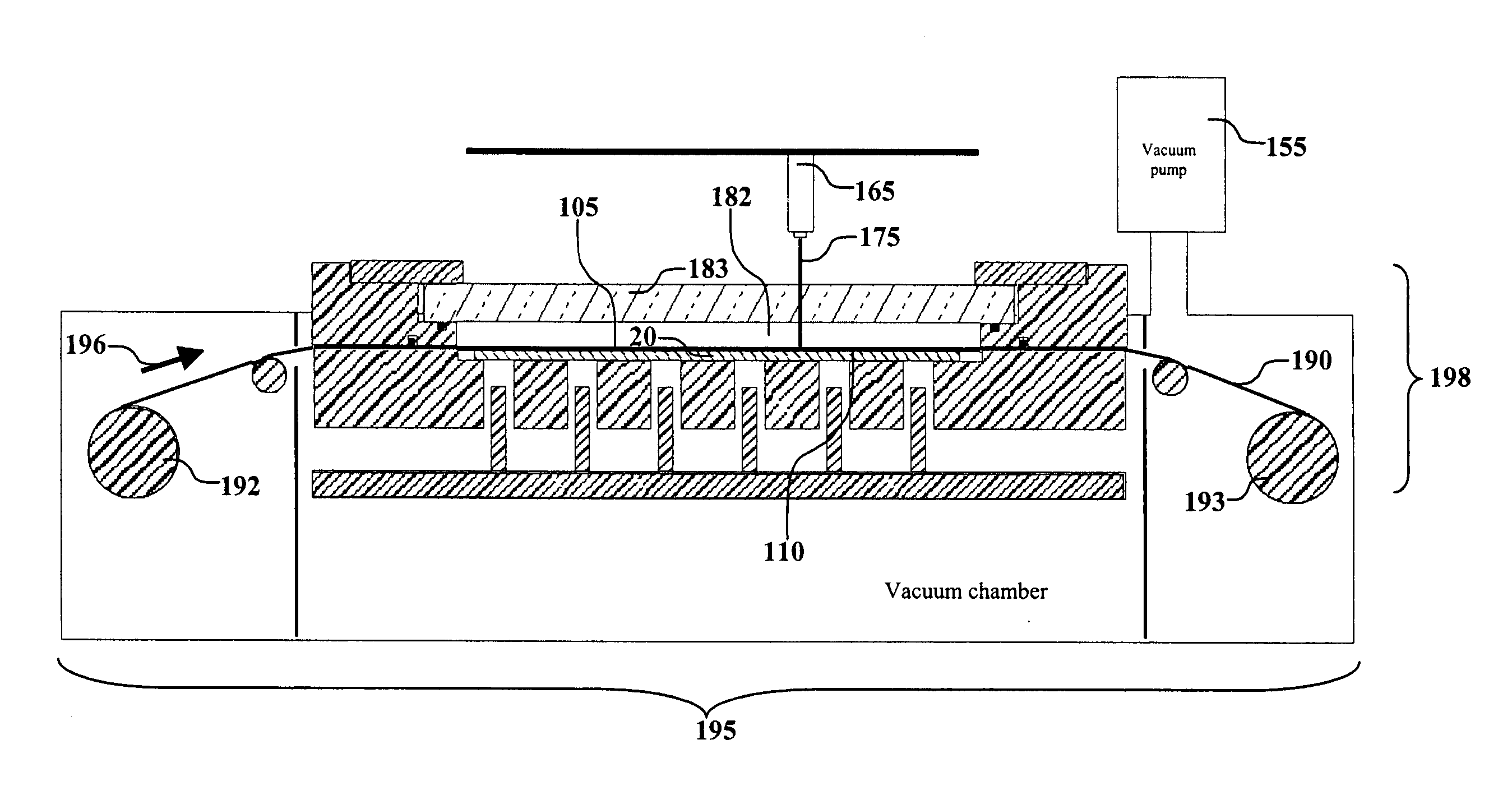
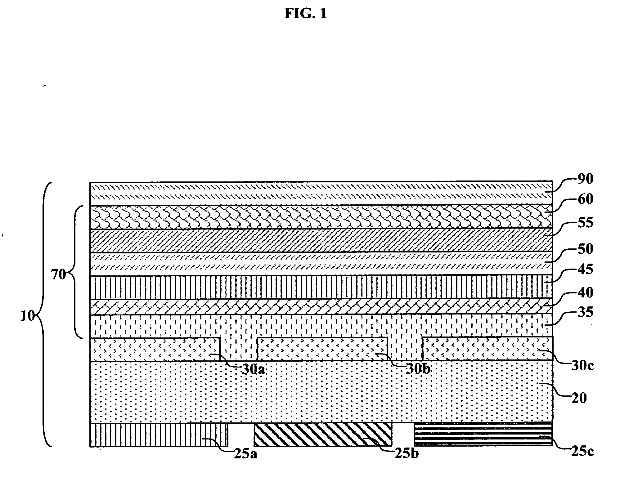
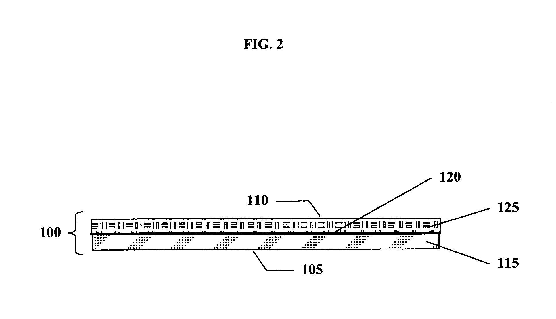
A method of making an OLED device includes forming a color filter array over one surface of a substrate; forming by an evaporation process an anode over the second surface of the substrate and a hole-transporting layer over the anode; moving one or more coated donor elements into a transfer position relative to the hole-transporting layer and transferring emissive material from the donor elements onto the hole-transporting layer to form a light-emitting layer which is capable of emitting white light; and coating by an evaporation process a cathode over the light-emitting layer.

Description

CROSS REFERENCE TO RELATED APPLICATIONS [0001] Reference is made to commonly assigned U.S. patent application Ser. No. 10 / 021,410 filed Dec. 12, 2001 by Bradley A. Phillips, et al., entitled “Apparatus for Permitting Transfer of Organic Material From a Donor to Form a Layer in an OLED Device”; commonly assigned U.S. patent application Ser. No. 10 / 224,182 filed Aug. 20, 2002 by Bradley A. Phillips, et al., entitled “Apparatus for Permitting Transfer of Organic Material from a Donor Web to Form a Layer In an OLED Device”; and commonly assigned U.S. patent application Ser. No. 10 / 647,499 filed Aug. 5, 2003 by Giana M. Phelan, et al., entitled “Correcting Potential Defects in an OLED Device”; the disclosures of which are incorporated herein by reference.FIELD OF THE INVENTION [0002] The present invention relates to white OLED devices with color filter arrays, and manufacturing thereof. BACKGROUND OF THE INVENTION [0003] An organic light-emitting diode device, also called an OLED device,...

Claims


Application Information

Patent Timeline
IPC IPC(8): B44C1/00B44C1/165H01L27/32H01L51/00H01L51/40H01L51/50H01L51/56H05B33/10
CPCH01L27/322H01L51/56H01L51/5036H01L51/0013C23C14/28C23C14/562C23C14/048H10K59/38H10K71/18H10K50/125H10K71/421H10K71/164H05B33/10H10K71/00
Inventor HATWAR, TUKARAM K.
Owner EASTMAN KODAK CO
Learn More