
Apparatus for separating particulates from a fluid stream

a technology of fluid stream and apparatus, applied in the direction of sedimentation settling tank, liquid displacement, separation process, etc., can solve the problems of increasing the likelihood of natural water contamination, increasing the strain on existing water transfer and treatment infrastructure, and locating particles and contaminants, so as to minimize the possibility of clogging, minimize the effect of exit blockage, and maximize the ability of particulate removal

Active Publication Date: 2005-07-07
CONTECH ENGINEERED SOLUTIONS
View PDF7 Cites 10 Cited by
  • Summary
  • Abstract
  • Description
  • Claims
  • Application Information

AI Technical Summary

Benefits of technology

The present invention provides a fluid separation system that can effectively remove particulate matter from a fluid without compromising fluid flow rate. The system includes a tank with a screen and a baffle to prevent clogging, and a second screen to capture floating particulate matter. The system also includes a collection weir to retain floating particulate matter. The invention aims to minimize clogging, prevent contamination, and reduce the amount of particulate matter in the fluid. The technical effects of the invention include improved separation of particulate matter from fluids and reduced clogging of fluid systems.

Problems solved by technology

If such diversion or treatment systems are not provided, particulates and contaminants located on or forming part of such structures may be carried by drain water or stormwater to the natural water bodies and contaminate them.
Land development produces increased levels of drain water and stormwater runoff, resulting in increased strain on existing water transfer and treatment infrastructure and an increased likelihood of natural water contamination.
Unfortunately, ineffectively designed separation systems fail to provide the best particulate removal and further fail to do so under flow rates that may not be particularly high.
Inline treatment systems of relatively modest size are particularly desirable for incorporating into existing fluid transfer systems, however, they may be prone to shorter maintenance cycles as a result of competing goals of reduced size, exit blockage minimization, and flow through capacity requirements.

Method used


Image

  • Apparatus for separating particulates from a fluid stream
  • Apparatus for separating particulates from a fluid stream
  • Apparatus for separating particulates from a fluid stream

Examples


Embodiment Construction

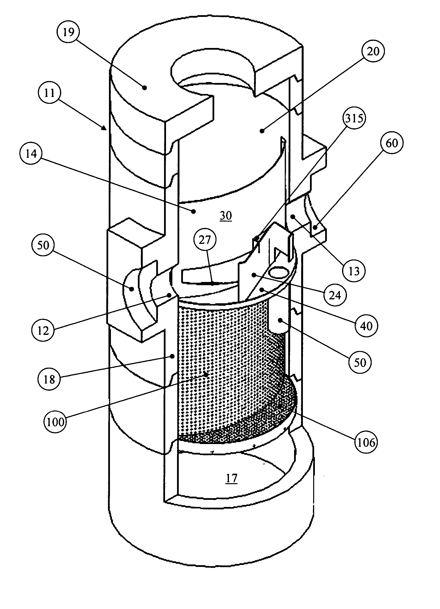
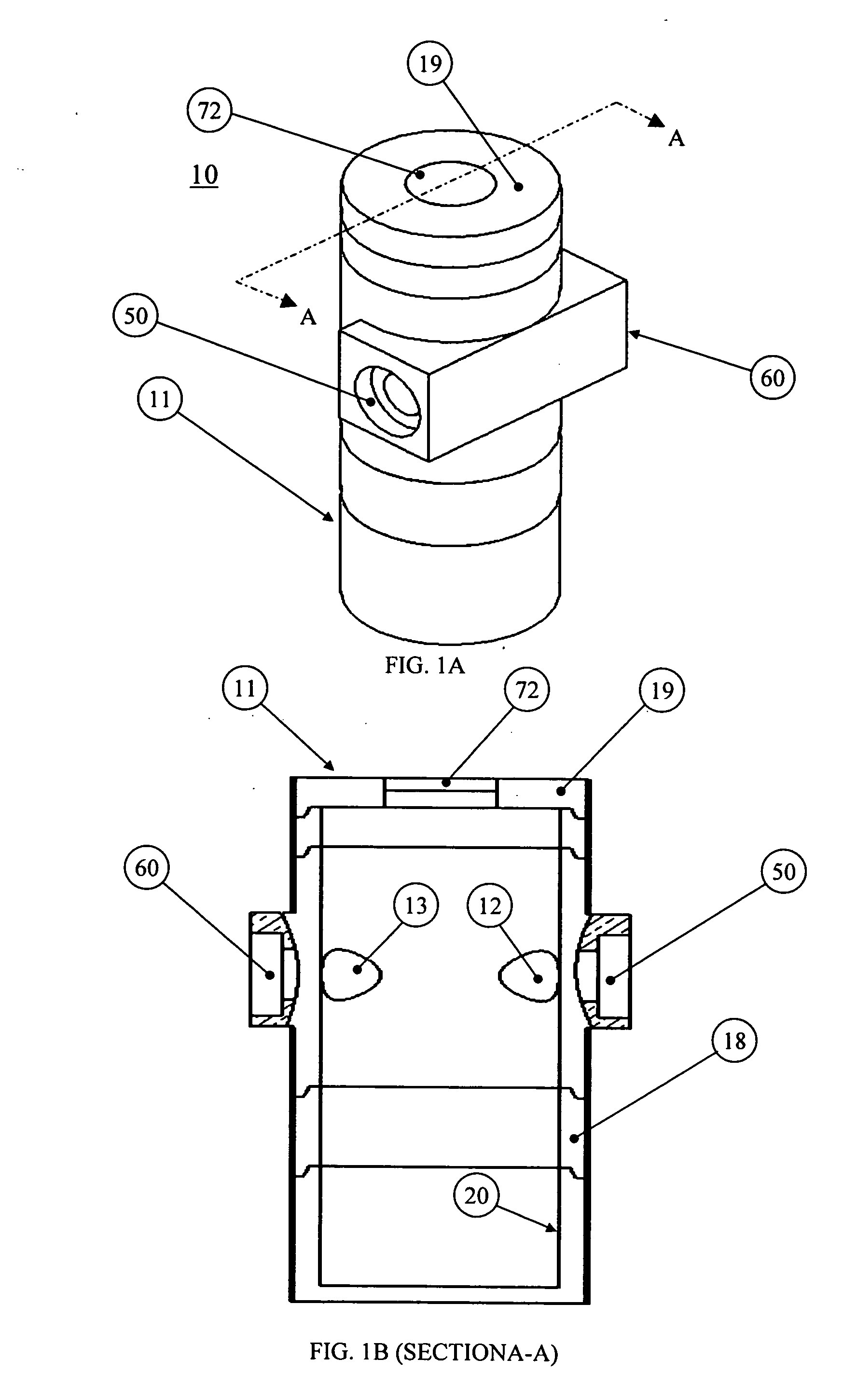
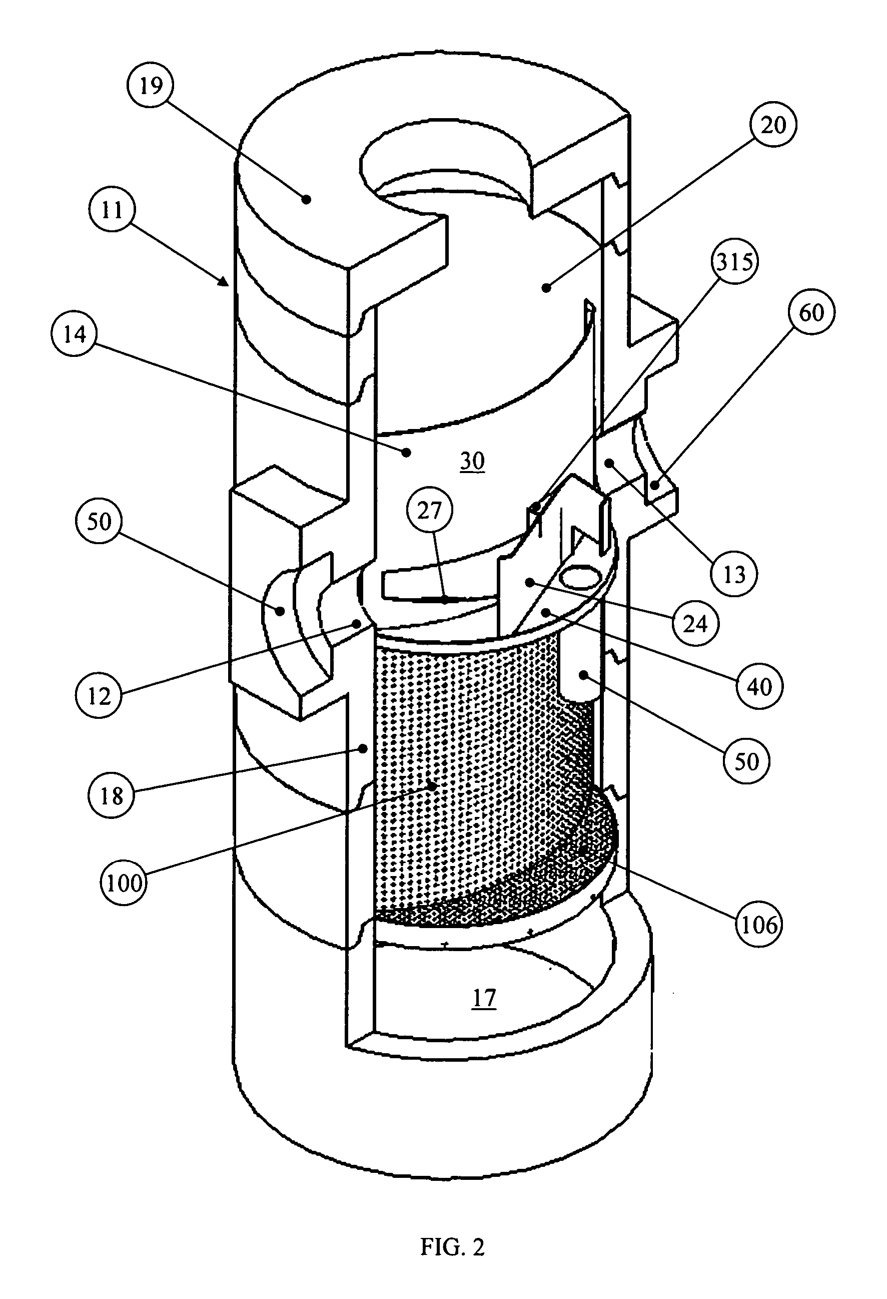
[0031] A separation system 10 including a screen apparatus of the present invention is illustrated in the accompanying drawings. As illustrated in FIGS. 1A and 1B, the system 10 includes a tank 11 having an inlet pipe socket 50 and an outlet pipe socket 60. The tank 11 is preferably made of concrete but may alternatively be fabricated in whole or in parts of metal, plastic, such as fiberglass, or other suitable materials. It may be fabricated of an existing manhole or manhole design and modified in the manner to be described herein. The inlet pipe socket 50 shown in FIG. 1A is used to connect the tank 11 to an upstream fluid source or transfer system, such as through an upstream conduit (not shown). Similarly, the outlet pipe socket 60 shown in FIG. 1A is used to connect the tank to a downstream fluid transfer system, such as through a downstream conduit (not shown). For example, the upstream fluid transfer system may include a drainage system from a roadway or a parking lot and the...


PUM

PropertyMeasurementUnit
conical shapeaaaaaaaaaa
heightaaaaaaaaaa
movementaaaaaaaaaa

Abstract

A screen apparatus for improved separation of particulates from a fluid stream. The screen is configured and arranged to filter relatively large particulates from the fluid stream as the fluid stream passes from a storage chamber of the tank to a tank outlet. The screen is removably affixed to a diverter, such as a baffle, used to divert a portion or all of the fluid into the storage chamber. The screen is preferably shaped to substantially conform to the shape of the diverter to aid in the smoothing of the fluid flow within the retention section of the tank. The screen may be entirely porous, or it may be non-porous at its leading edge to minimize particulate build-up at the transition from the tank interior wall to the screen. The apparatus may optionally include a second screen to provide additional filtering of floating particulates as the fluid level in the tank exceeds the crown elevation of the inlet. The second screen may be substantially horizontally oriented and may be combined with a collection weir. Alternatively, the second screen may be conical in shape. A high flow bypass arrangement for the separation system may include an upper baffle and a lower baffle or a screen instead of the lower baffle. The upper baffle is set closer to the center of the tank than the lower baffle or screen, thereby providing more volume for flow diversion behind the upper baffle.

Description

CROSS REFERENCE TO RELATED APPLICATION [0001] This application is a continuation-in-part of co-pending U.S. patent application Ser. No. 10 / 664,376, filed Sep. 17, 2003, entitled “APPARATUS FOR SEPARATING FLOATING AND NON-FLOATING PARTICULATE FROM A FLUID STREAM” owned by a common assignee. The content of that application is incorporated herein by reference and priority is claimed therein.BACKGROUND OF THE INVENTION [0002] 1. Field of the Invention [0003] The present invention relates to systems for separating particulates from fluids such as drain water and stormwater. Such particulates include particulates that float under most fluid movement conditions, particulates that do not float under most fluid movement conditions, and particulates that may be caught up in the fluid stream when the fluid is flowing, but that may otherwise float or be suspended within the fluid when the fluid is substantially stagnant. More particularly, the present invention relates to a separation system th...

Claims


Application Information

Patent Timeline
Patent Type & Authority Applications(United States)
IPC IPC(8): B01D21/02
CPCB01D21/02B01D21/2411B01D21/2444B01D21/245B01D21/0006
Inventor COBB, DANIEL P.ALLEN, VAIKKO P. IIRICHARDSON, JOHN E.CHARLTON, DAVID R.BERG, DEREK M.
Owner CONTECH ENGINEERED SOLUTIONS
Learn More