Exposure apparatus and device manufacturing method

Inactive Publication Date: 2005-07-07
CANON KK
View PDF15 Cites 836 Cited by
  • Summary
  • Abstract
  • Description
  • Claims
  • Application Information

AI Technical Summary

Benefits of technology

[0010] Accordingly, it is an exemplary object of the present invention to provide an exposure apparatus that precisely and stably controls the temperature

Problems solved by technology

However, the temperature sensor 108a cannot be arranged on the substrate, and thus it is impossible to detect the fluid's temperature at the exposure area.
The imprecise temperature control at the exposure area deteriorates the resolution performance since the fluid's refractive index fluctuates with the fluid's temperature changes at the exposure area.
Use of the temperature control shown in FIG. 5 for the immersion type projection exposure apparatus tha

Method used


Image

  • Exposure apparatus and device manufacturing method
  • Exposure apparatus and device manufacturing method
  • Exposure apparatus and device manufacturing method

Examples


first embodiment

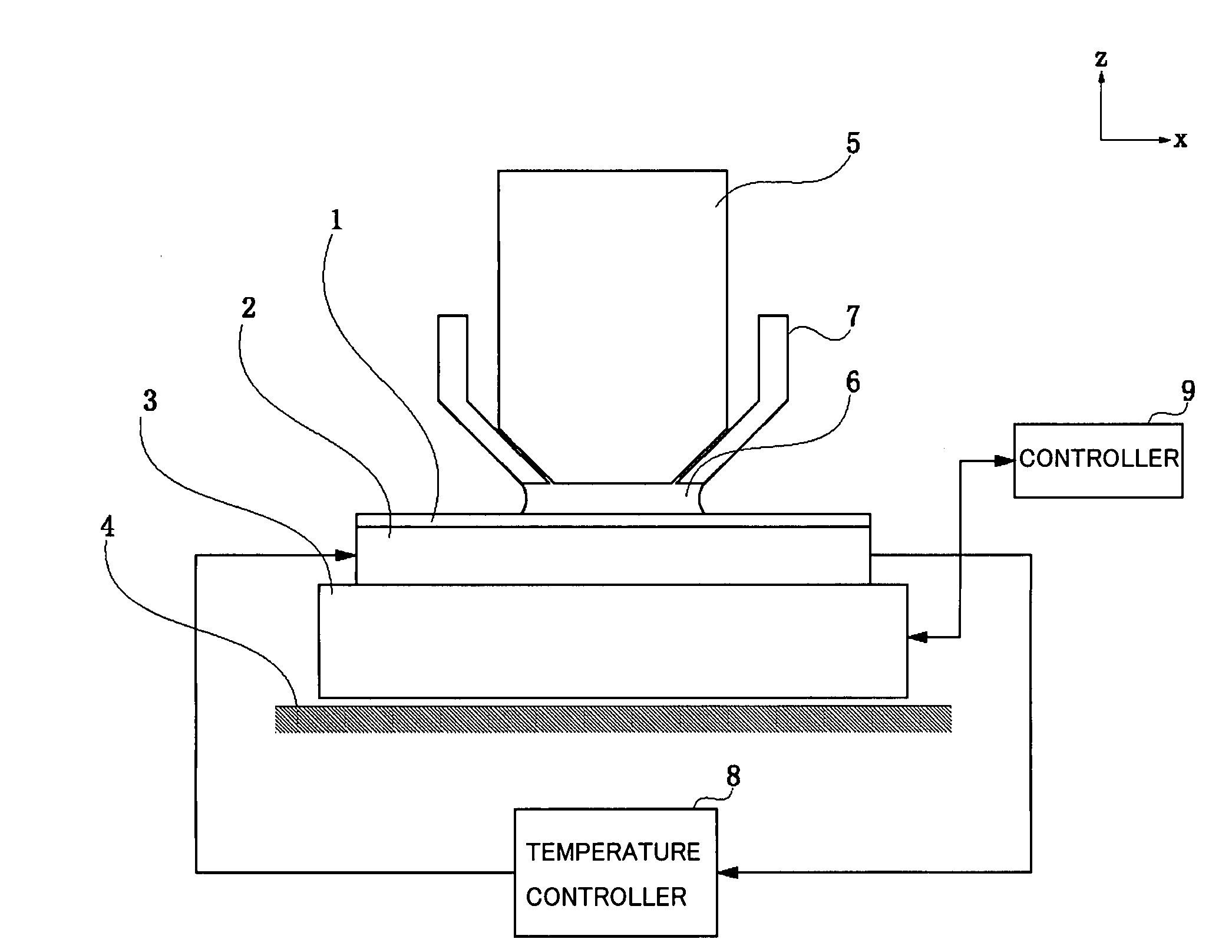
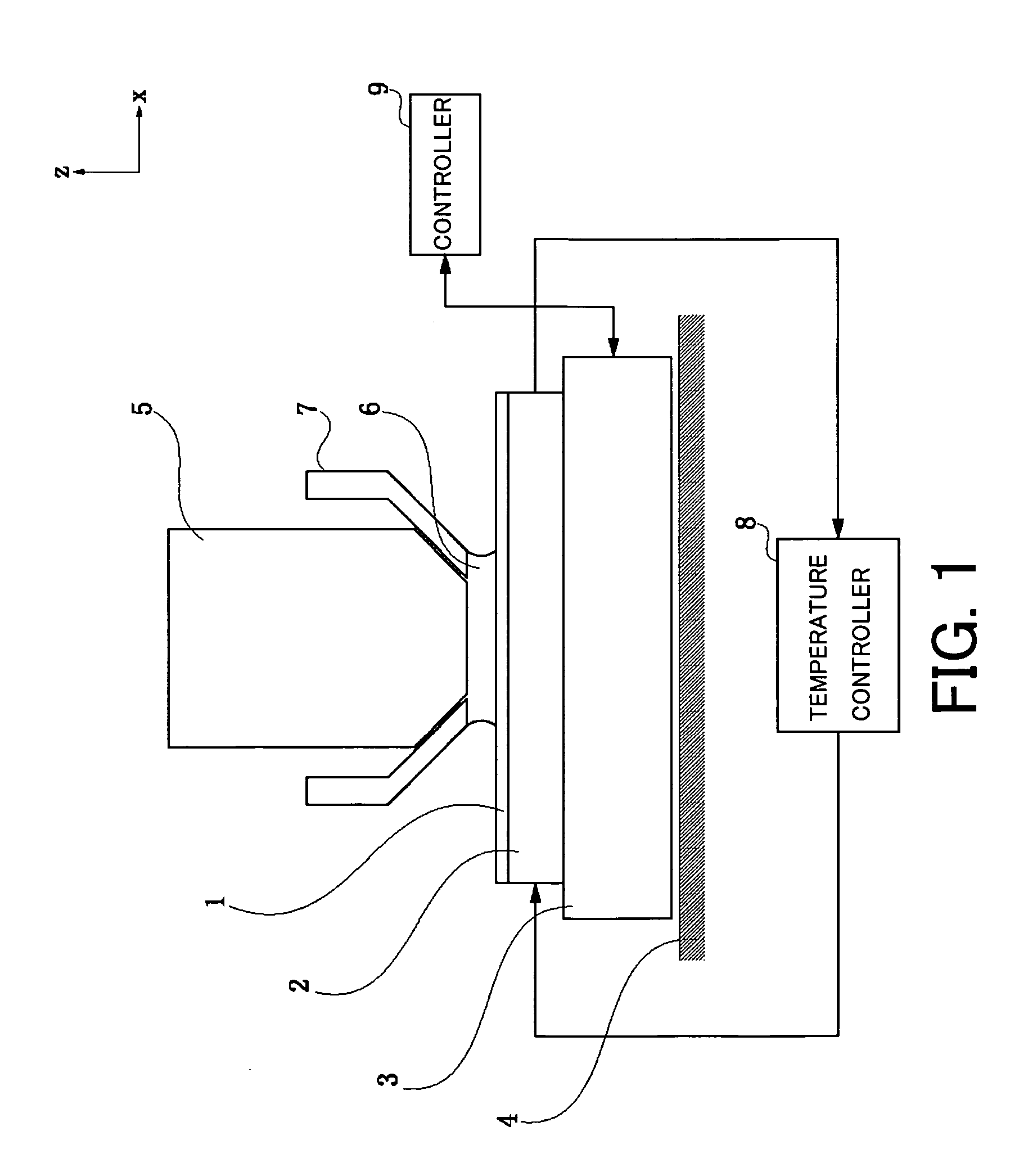
[0024]FIG. 1 is a view for explaining a structure of an exposure apparatus according to the present invention.

[0025] In FIG. 1, 1 denotes a substrate, such as a wafer. 2 denotes a substrate chuck as a holder that holds the substrate 1. A holding method of the substrate includes a vacuum or electrostatic absorption. 3 denotes a substrate stage, and preferably has a six-axis driving shafts in and around XYZ directions. 4 denotes a stage stool, and the substrate stage 3 is driven on the stage stool 4 via the air bearing or magnetic levitation. 5 denotes a projection optical system for projecting a pattern of a reticle (mask) (not shown) onto the substrate. The reticle is located above the projection optical system 5, placed on the reticle stage, and scanned in synchronization with the substrate stage 3, although FIG. 1 omits the reticle. An illumination optical system and a light source for the exposure light are also located above the reticle, but FIG. 1 omits these components simila...

second embodiment

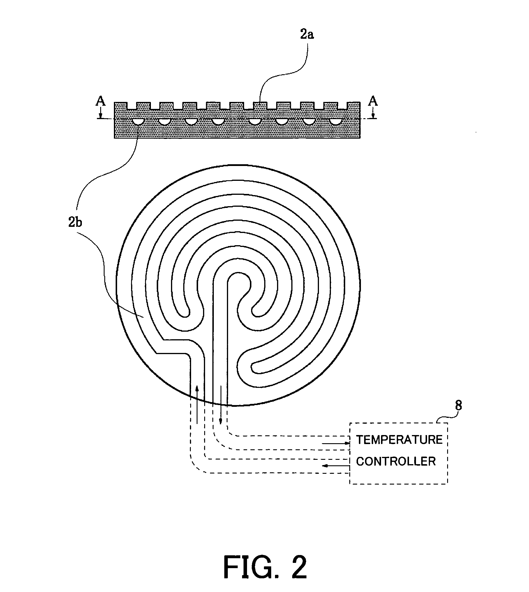
[0030] The first embodiment flows the water whose temperature has been controlled by the temperature controller 8 over almost the entire surface in the substrate chuck 2, and controls the temperatures of the substrate chuck 2 and the fluid 6.

[0031] On the other hand, this embodiment quadrisects the water conduit in the substrate chuck 2, and provides more precise temperature control. Similar to the first embodiment, one substrate chuck 2 is formed by pasting two sheets to each other. A structure of the exposure apparatus other than the temperature controller 8 is almost similar to that of the first embodiment, and a description thereof will be omitted.

[0032]FIG. 3 is a view for explaining the substrate chuck 2 in the second embodiment, although FIG. 3 omits the detailed water conduit in the substrate chuck 2. As shown by broken lines, the inside of the substrate chuck 2 is divided into first to fourth quadrants, and the water temperature-controlled by the temperature controller 8 ...

third embodiment

[0038] The first and second embodiment controls the temperature of the fluid 6 by controlling the temperature of the substrate chuck 2.

[0039] On the other hand, this embodiment controls the temperature of the optical element 5a in the projection optical system 5, which is closest to the substrate 1, and thereby controls the temperature of the fluid 6 between the optical element 5a and the substrate 1. A structure of the exposure apparatus other than the temperature controller 8 is similar to that of FIG. 1, and a description thereof will be omitted.

[0040]FIG. 4 is a view for explaining a temperature control structure of a third embodiment. In FIG. 4, 5a denotes a final lens, which is an optical element in the projection optical system 5 closest to the substrate 1. 5b denotes a support part for supporting the final lens 5a. The support member 5b is held in the projection optical system 5. A description will now be given of the temperature-controlled part that is indicated by a brok...


PUM


Abstract

An exposure apparatus includes a projection optical system for projecting a pattern on a reticle onto a substrate, the projection optical system including an optical element closest to the substrate, an illumination optical system for illuminating the reticle using light from a light source, and a temperature controller for controlling a temperature of the optical element and thereby a temperature of a fluid that is filled in a space between the optical element in the projection optical system and the substrate, the exposure apparatus exposing the substrate via said projection optical system and the fluid.

Description

BACKGROUND OF THE INVENTION [0001] The present invention relates generally to an exposure apparatus that exposes a pattern of an original, such as a reticle, onto a substrate, such as a wafer, and a device manufacturing method that uses the exposure apparatus to manufacture various devices, such as a semiconductor chip and a liquid crystal panel, and more particularly to an immersion type exposure apparatus that fills the fluid in the space between the projection optical system and substrate and exposes the substrate via the fluid, and a device manufacturing method using such an exposure apparatus. [0002] An immersion type exposure apparatus fills the fluid in the space between the substrate and an optical element in the projection optical system, which is closest to the substrate, and increases a numerical aperture (“NA”) using the high refractive index of the fluid. Therefore, the immersion type exposure apparatus is expected to provide the high resolution. [0003] Proposed for the...

Claims


Application Information

Patent Timeline
IPC IPC(8): G02B13/24G03B27/52G03F7/20H01L21/00H01L21/027
CPCG03B27/52G03F7/70891G03F7/70341B60H1/00585B60H1/00985B60Y2200/30B61D27/0018Y02T30/00
Inventor TOKITA, TOSHINOBU
Owner CANON KK
Why Eureka
Try Eureka