Device for inductively transmitting electrical energy

a technology of inductive transmission and electrical energy, which is applied in the direction of inductance, power rails, electric vehicles, etc., can solve the problems of inconvenient connection of a second cable to such a junction, complicated separation of an installed cable and the like, and the cost of providing an additional route segment with a separate power feed is equally high, so as to achieve the effect of simple and less expensiv

Inactive Publication Date: 2005-07-07
CONDUCTIX WAMPFLER
View PDF5 Cites 12 Cited by
  • Summary
  • Abstract
  • Description
  • Claims
  • Application Information

AI Technical Summary

Benefits of technology

[0009] In light of the foregoing prior art, the invention aims to propose a simpler and less expensive means of realizing a variable path layout for a device for inductively transmitting electrical energy.

Problems solved by technology

Consequently, it is very complicated to separate an installed cable and to connect a second cable to such a junction.
The alternative solution of providing the additional route segment with a separate power feed is equally costly.
A related problem is the realization of switches, i.e., route junctions for rail-bound vehicles at which a vehicle can selectively travel in one of several directions.

Method used


Image

  • Device for inductively transmitting electrical energy
  • Device for inductively transmitting electrical energy
  • Device for inductively transmitting electrical energy

Examples


Embodiment Construction

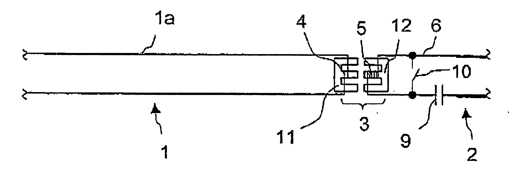
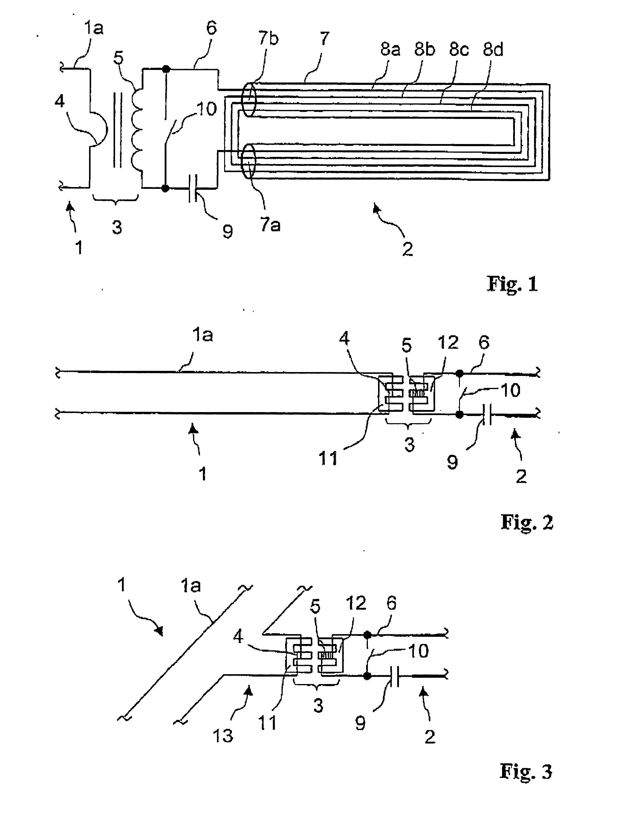
[0023]FIG. 1 schematically shows the inductive coupling of two electrically separated conductor loops 1 and 2 in accordance with the invention, wherein only a small portion of the conductor loop 1 is visible in FIG. 1 and the conductor loop 2 is drawn much shorter in relation to its width. Both conductor loops 1 and 2 respectively form the primary side of a system for inductively transmitting electrical energy to a mobile load that draws the energy from the magnetic field generated by the current in the respective conductor loop 1 or 2 by means of a pickup. In this case, the conductor loop 1 is connected to not-shown supply electronics that supply current to the conductor loop 1. However, the current can only be induced in the conductor loop 2 by the current in the conductor loop 1. For this purpose, the two conductor loops 1 and 2 are coupled by means of a transformer 3. Since the conductor loop 1 lies on the primary side of this transformer 3 and the conductor loop 2 on the second...


PUM

PropertyMeasurementUnit
electrical energyaaaaaaaaaa
lengthaaaaaaaaaa
input impedanceaaaaaaaaaa

Abstract

A device for inductively transmitting electrical energy to at least one mobile load, with at least one primary conductor that extends along a designated path of the load in the form of a conductor loop and from which a secondary conductor arranged on the load is able to draw electrical energy. At least two conductor loops are provided that are electrically separated from one another and respectively assigned to different segments of the path. The conductor loops are arranged relative to one another so that electrical energy intended for the load can be transmitted from a first conductor loop to at least a second conductor loop due to inductive coupling between the conductor loops. A section of the second conductor loop that is inductively coupled contains a larger number of windings than that of the first conductor loop. The second conductor loop includes of a series of partial loops that extend parallel to one another.

Description

RELATED APPLICATION [0001] This application is a continuation of International Application No. PCT / EP03 / 01509, filed Feb. 14, 2003, the contents of which are here incorporated by reference in their entirety. The benefits of 35 USC Section 120 are here claimed. BACKGROUND OF THE INVENTION [0002] 1. Field of the Invention [0003] The invention pertains to a device for inductively transmitting electrical energy. [0004] 2. Prior Art [0005] A device of this type is known, for example, from WO 92 / 17929 and serves for transmitting electrical energy to at least one mobile load without mechanical or electrical contact. This device consists of a primary part and a secondary part that are electromechanically coupled similarly in principle to a transformer. The primary part comprises supply electronics and a conductor loop laid along a path. One or more pickups and the corresponding pickup circuitry form the secondary part. In contrast to a transformer, in which the primary and the secondary par...

Claims


Application Information

Patent Timeline
Patent Type & Authority Applications(United States)
IPC IPC(8): B60L5/00B60M1/32H01F38/14H02J5/00
CPCB60L5/005B60M1/32B60L2200/26H02J5/005H01F38/14H02J50/12H02J50/80
Inventor GREEN, ANDREWTHOMPSON, KEITHWECHLIN, MATHIAS
Owner CONDUCTIX WAMPFLER
Why Eureka
Try Eureka