

Method and apparatus for beam steering in a wireless communications systems
a wireless communication system and beam steering technology, applied in the field of beam steering, can solve the problems of limiting the maximum achievable antenna gain, difficult to maintain precision with beam steering, and high cost of active beam steering systems, so as to minimize the cost of the system
- Summary
- Abstract
- Description
- Claims
- Application Information
AI Technical Summary
Benefits of technology
Problems solved by technology
Method used
Image

Examples
Embodiment Construction
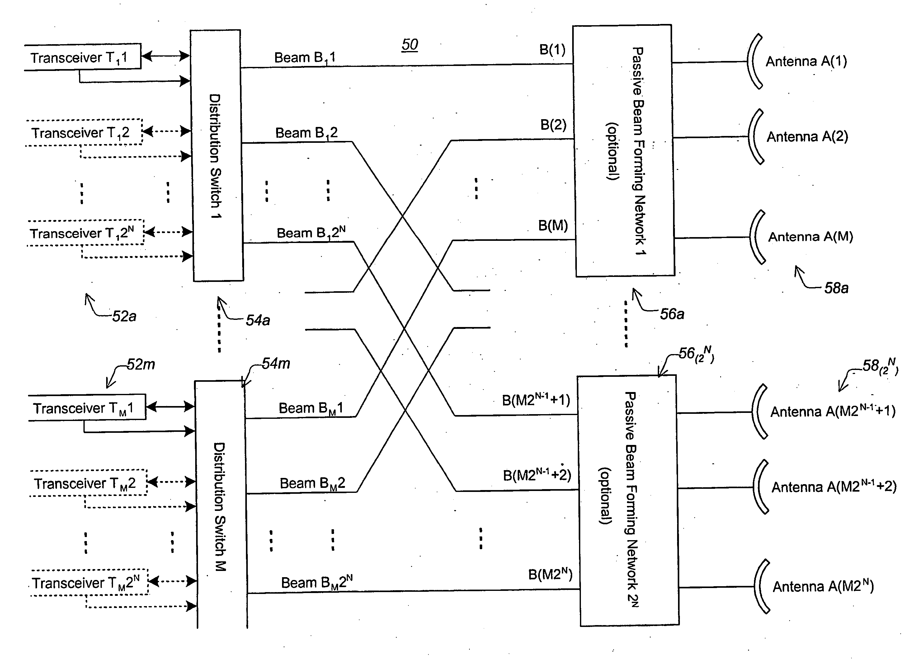
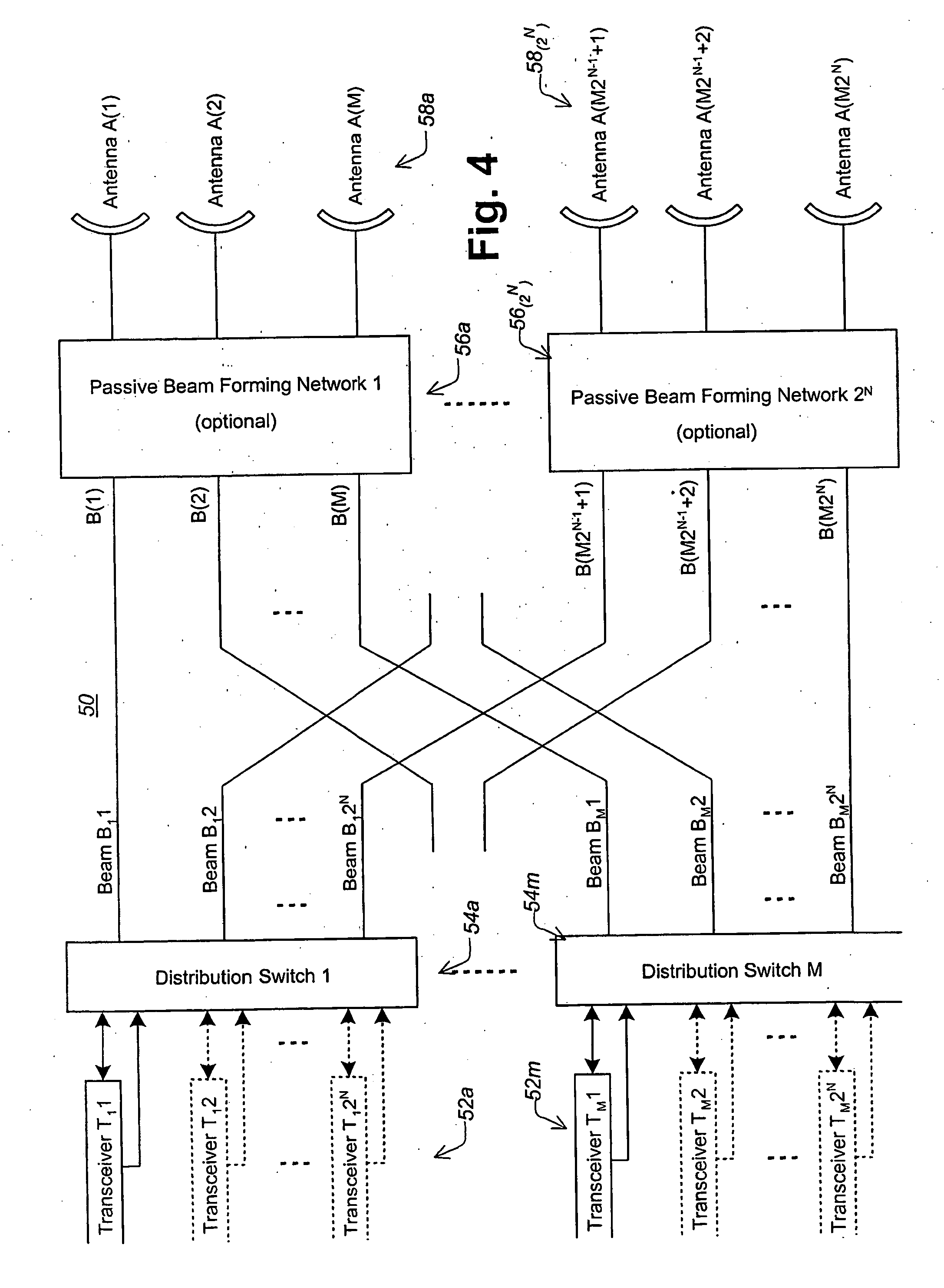
[0046] Referring to FIG. 4, there is illustrated a wireless system in accordance with an embodiment of the present invention. The wireless system 50 includes a plurality of transceivers 52a-m coupled to a corresponding plurality of distribution switches 54a-m. Distribution switches 54a-m each having 2N outputs for coupling to corresponding inputs of 2n passive beam forming networks 56 each passive beam-forming network 56 is connected to a plurality M of antennas 58. Each of the plurality of transceivers 56a-56m may include 2N transceivers.
[0047] The system of FIG. 4 thus uses M2N high-gain antennas 58 that are first grouped in 2N groups of M antennas each. Each group of M antennas is processed by one beam-forming network 56 to form M high-gain beams. Note, that an embodiment of the invention may be applied without the beam-forming network, in which the beam width and gain are equal to the antenna angle and gain. However, in most cases when a large number of antennas are used the be...
PUM
 Abstract
Description
Claims
Application Information