Multiple-angle scissor blade

a scissor blade and multi-angle technology, applied in the field of laparoscopic scissors, can solve the problem of no heat-treatment step afterwards, and achieve the effect of increasing tension and giving strength

Inactive Publication Date: 2005-07-07
APPL MEDICAL RESOURCES CORP
View PDF14 Cites 96 Cited by
  • Summary
  • Abstract
  • Description
  • Claims
  • Application Information

AI Technical Summary

Benefits of technology

[0008] The cutting operation may include cutting at least one of a body tissue, a suture and a surgical staple. During the cutting operation, the blades progressively move over each other to provide a point contact along the cutting edges. It is appreciated that the blades may be thickened in a number of locations and combinations including: (1) one blade could be thicker than the other to force the opposing blade to flex; (2) both blades could be thicker at the body or throat sections to give more strength when cutting staples; (3) each blade could be thickened on one side or the other to stiffen certain locations; and (4) the tips of each blade could be thicker than the body or throat sections to provide increased tension at the tips.

Problems solved by technology

Additionally, there is no heat-treating step afterwards because it was done prior to grinding and cutting.

Method used


Image

  • Multiple-angle scissor blade
  • Multiple-angle scissor blade
  • Multiple-angle scissor blade

Examples


Embodiment Construction

[0018] The following description refers to the accompanying drawings that illustrate the embodiments of the invention. Other embodiments are possible and modifications may be made to the embodiments without departing from the spirit and scope of the invention. Thus, the following description is not meant to limit the invention.

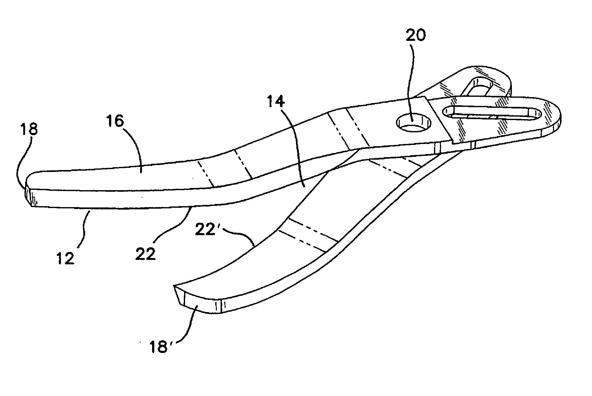
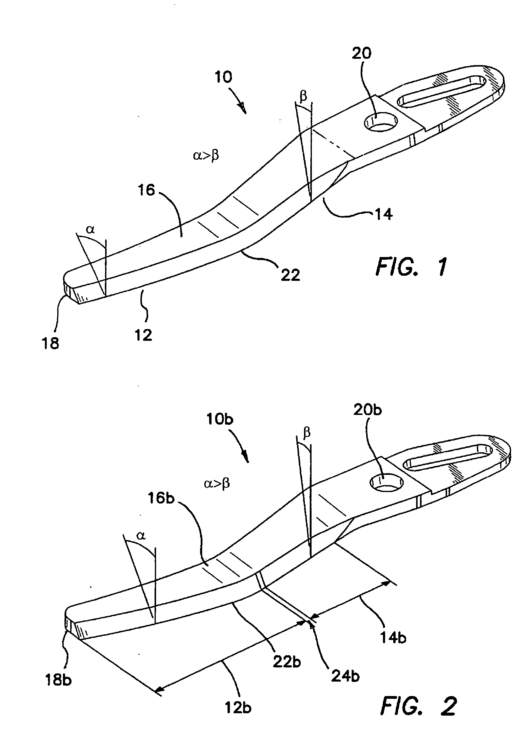
[0019] Referring now to the drawings, and in particular to FIG. 1, there is shown an exemplary blade 10 of a scissors in accordance with the first embodiment of the invention. The blade 10 includes a tip portion 12, a body or throat portion 14, an outer surface 16, an inner surface 18, a cutting edge 22 and a pivot area 20. The cutting edge 22 forms an angle with the outer surface 16 along the length of the blade 10 such that tension at the tip portion 12 is about the same as tension at the body or throat portion 14. The function and effectiveness of the scissor blades depend heavily on the tension and angle the cutting surfaces are to each other. The blades ...


PUM

PropertyMeasurementUnit
lengthaaaaaaaaaa
tensionaaaaaaaaaa
angleaaaaaaaaaa

Abstract

The invention is directed to a pair of laparoscopic scissors, comprising a pair of blades connected at a pivot, each of the blades having a length, a tip portion, a body portion, an outer surface, an inner surface and a cutting edge, the cutting edge forming an angle with the outer surface along the length of the blade such that tension during a cutting operation at the tip portion is about the same as tension at the body portion during the cutting operation. The angle formed may be greater at the tip portion which continuously decreases over the length of the blade. The tip portion may have a first body thickness and the body portion may have a second body thickness different from the first body thickness. During the cutting operation, the blades progressively move over each other to provide a point contact along the cutting edges. The blades may be thickened in a number of locations and combinations including: (1) one blade could be thicker than the other to force the opposing blade to flex; (2) both blades could be thicker at the body portions to give more strength when cutting staples; (3) each blade could be thickened on one side or the other to stiffen certain locations; and (4) the tips of each blade could be thicker than the body portions to provide increased tension at the tips. In another aspect of the invention, a process of manufacturing the pair of scissors of the invention is disclosed, comprising the steps of form grinding the blades into a desired shape from a pre-hardened block of material, and sharpening the cutting edges of the blades. The blades may also be formed through other processes including wire EDM, laser cutting, waterjet cutting, machining, cast or metal injection molding, and other independent profile manufacturing processes. The manufacturing process of the invention is beneficial in that each profile can be accurately controlled, and the parts will be exact every time.

Description

[0001] This is a non-provisional application claiming the priority of provisional application Ser. No. 60 / 517,729, filed on Nov. 5, 2003, entitled “Multiple-Angle Scissor Blade,” which is fully incorporated herein by reference.BACKGROUND OF THE INVENTION [0002] 1. Field of the Invention [0003] This invention generally relates to laparoscopic scissors and, more particular, to laparoscopic scissors having multiple cutting angles and multiple thicknesses. [0004] 2. Discussion of Related Art [0005] During surgery, surgeons will typically need to cut into a multitude of objects such as tissues, suture and metal staples. A goal in the design of scissors and, in particular, in the design of scissors' blades is to optimize its effectiveness in cutting through different objects. For cutting through soft tissues, a large angle ground into the blade is most effective. That is, when sharp edges shear against each other, any tissue which comes between the blades of the scissors will get cut. The...

Claims


Application Information

Patent Timeline
Patent Type & Authority Applications(United States)
IPC IPC(8): A61B17/32
CPCA61B17/320016A61B17/3201B26B13/08B26B13/06B24B3/52
Inventor AHLBERG, RUSSELL E.JOHNSON, GARY M.OKIHISA, DAVID
Owner APPL MEDICAL RESOURCES CORP
Why Eureka
Try Eureka