
Method for manufacturing an item

Inactive Publication Date: 2005-07-07
AGENTWARE SYST
View PDF12 Cites 39 Cited by
  • Summary
  • Abstract
  • Description
  • Claims
  • Application Information

AI Technical Summary

Benefits of technology

[0007] It is an object of the present invention to provide a method for manufacturing an item which enhances the efficiency of the manufacturing process.
[0008] It is another object of the present invention to provide a method for manufacturing an item which coordinates the delivery of components such that the efficiency of the manufacturing process is enhanced.
[0009] It is still another object of the present invention to identify information concerning each of the components used in manufacturing an item and coordinate that information so as to facilitate delivery of the components at such a time to enhance the efficiency of the manufacturing process.
[0010] It is still a further object of the present invention to transmit information concerning the delivery and use of components in a manufacturing process to a supplier of such components to facilitate delivery of the components to the manufacturing line at such at time to enhance the efficiency of the manufacturing process. SUMMARY OF THE INVENTION
[0011] According to a first aspect of the present invention, a method is provided for manufacturing an item. The method comprises the steps of creating a build schedule; creating a first portion of the item for manufacture; causing the first portion of the item to pass in close proximity to a first individual; which said individual assembles at least one of the several components on the first portion; notifying a second individual of the existence and location of the first portion of the item proximate to the first individual; causing the first portion of the item to pass in close proximity to the second individual whereby said second individual assembles at least one of the several components onto the first portion of the item. The method further includes applying dataforms or other such markings on individual components to uniquely identify them and, through such markings, tracking the application of those components to the item being manufactured at each manufacture step. Moreover, the information associated with the components as they are tracked through the manufacture process is used to maintain and enhance the efficient operation of the assembly line. These and other aspects, features, and advantages of the present invention will become apparent from a reading of the following detailed description of the preferred embodiment of the invention and by reference to the following drawings.

Problems solved by technology

While the traditional assembly line process does allow efficient use of resources, modem manufacturing has evolved to reveal substantial limitations in this process.
Coordinating the assembly of this wide array of components has led to a substantial decrease in line efficiency.
Moreover, the assembly line process is further complicated by the fact that a build schedule for any one or more of the models may be changed or updated frequently.
Frequently, the “build schedule” must be dynamically altered or changed due to difficulties or occurrences, which arise after the build schedule has been created.
For example, faulty components may have been identified which prevent a certain type of vehicle to from being built in accordance with the build schedule.
Also, changes in types of components or in the delivery schedules of the components may require modification of a build schedule.
Whenever the component transport schedule is not modified to reflect these “build schedule changes,” or is incorrectly modified, the assembly line process may be delayed causing substantial inefficiencies.

Method used


Image

  • Method for manufacturing an item
  • Method for manufacturing an item
  • Method for manufacturing an item

Examples


Embodiment Construction

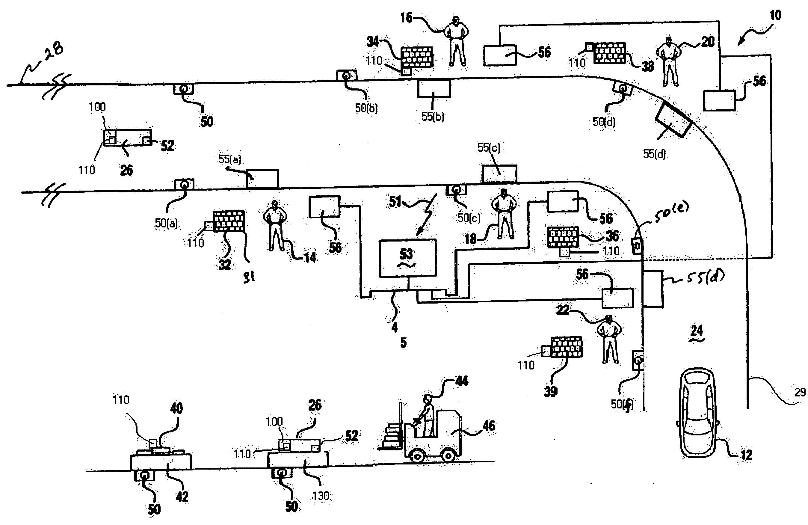
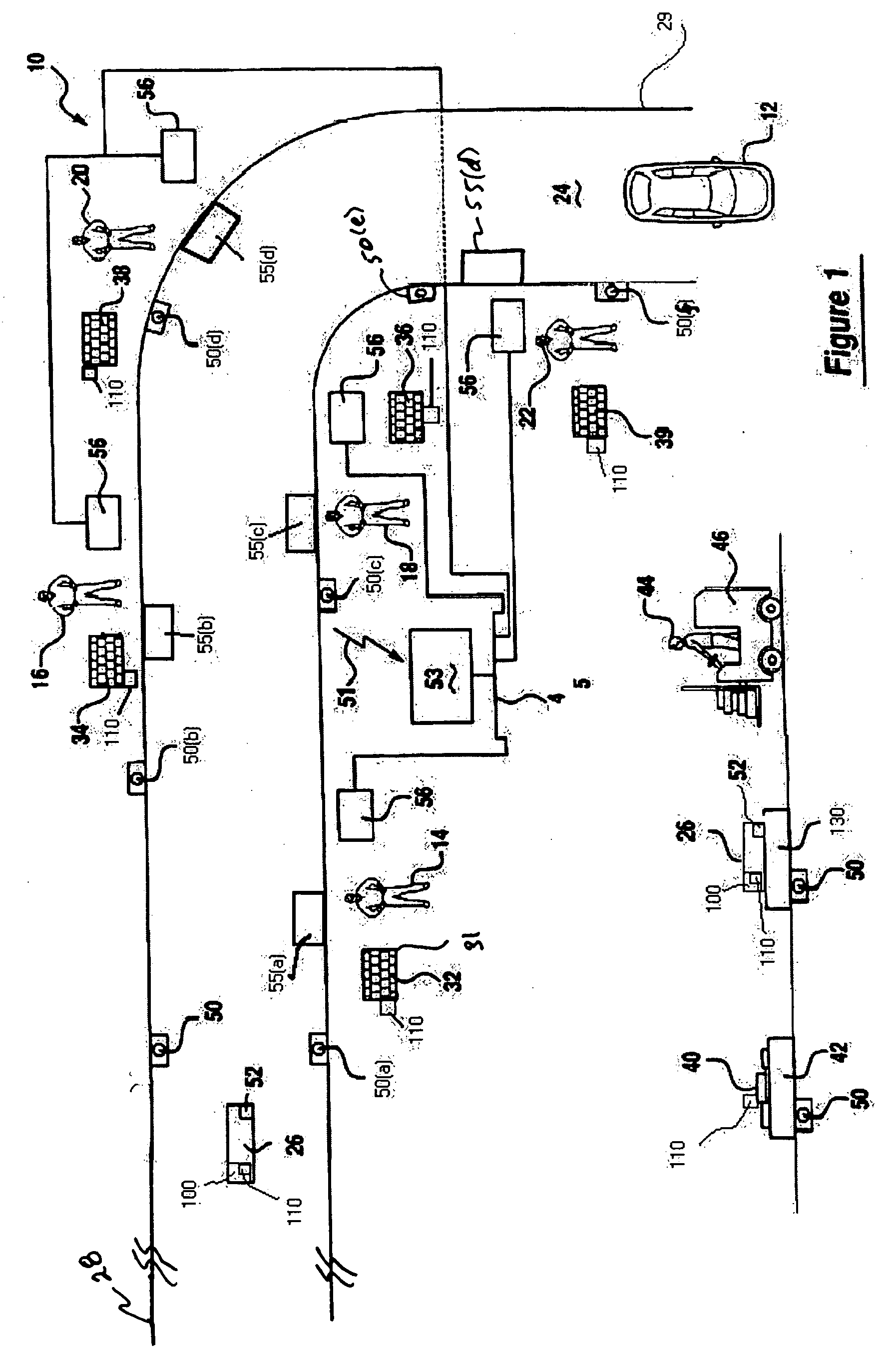
[0018] Referring now to FIG. 1, there is shown a vehicle manufacturing or assembly line 10 which is adapted to produce a vehicle 12. It should be appreciated that while assembly line 10 is, in this example, adapted to produce a vehicle 12, assembly line 10 could also be adapted to selectively produce other products and / or items (e.g., engines, transmissions, toasters, computers, etc.) which are susceptible of being manufactured on an assembly line basis and that the methodology of the present invention is not limited to the manufacture and / or assembly of a vehicle. Assembly line 10 includes several individuals or “operators”14, 16, 18, 20, and 22 respectively who are uniquely positioned in close proximity to a transport assembly or member 24 (e.g., a conveyor belt or assembly line). A first portion 26 of a vehicle 12 (e.g., a previously formed body or frame assembly) is placed at the beginning or “entry point”28 of the conveyor 24 and is sequentially and subsequently transported in ...


PUM


Abstract

According to a first aspect of the present invention, a method is provided for manufacturing an item. The method comprises the steps of creating a build schedule; creating a first portion of the item for manufacture; causing the first portion of the item to pass in close proximity to a first individual; which said individual assembles at least one of the several components on the first portion; notifying a second individual of the existence and location of the first portion of the item proximate to the first individual; causing the first portion of the item to pass in close proximity to the second individual whereby said second individual assembles at least one of the several components onto the first portion of the item. The method further includes applying dataforms or other such markings on individual components to uniquely identify them and, through such markings, tracking the application of those components to the item being manufactured at each manufacture step. Moreover, the information associated with the components as they are tracked through the manufacture process is used to maintain and enhance the efficient operation of the assembly line. These and other aspects, features, and advantages of the present invention will become apparent from a reading of the following detailed description of the preferred embodiment of the invention and by reference to the following drawings.

Description

FIELD OF THE INVENTION [0001] The present invention generally relates to a method for manufacturing or assembling an item and more particularly to a method for manufacturing or assembling an item, such as a vehicle, which requires the assembly of a relatively large number of components. BACKGROUND OF THE INVENTION [0002] Items, such as vehicles, are typically manufactured or assembled by the use of a relatively large number and variety of components such as, for example, engines, wheels, wiring harnesses, sun roofs, and hoods. Oftentimes, an “assembly line” is used to manufacture such vehicles or other items. An assembly line is a well known arrangement whereby, for example, various components of a vehicle are operatively placed upon the body or frame of the vehicle at various stations or locations of the assembly line. In this manner, each station or location corresponds to a unique stage of the overall vehicle assembly process and requires the placement of a unique component or th...

Claims


Application Information

Patent Timeline
IPC IPC(8): G05B19/12G05B19/418G06F19/00
CPCG05B19/12G05B19/41805G05B2219/31027Y10T29/53087G05B2219/31307Y10T29/49829G05B2219/31034Y02P90/02
Inventor POPPLEWELL, HAL
Owner AGENTWARE SYST
Learn More