Apparatus and method for detecting vehicle location in navigation system

a technology of navigation system and apparatus, applied in traffic control systems, navigation instruments, instruments, etc., can solve the problems of wasting fuel, traffic congestion, and wasting more than 14.35 billion liters of fuel per year, and 2.7 billion hours of work tim

Active Publication Date: 2005-07-07
LG ELECTRONICS INC
View PDF5 Cites 84 Cited by
  • Summary
  • Abstract
  • Description
  • Claims
  • Application Information

AI Technical Summary

Benefits of technology

[0024] Accordingly, a first object of the present invention is to provide an apparatus and method for detecting a vehicle location in a navigation system, wherein the vehicle location can be precisely detected in such a manner that an error included in a detected vehicle location will not be accumulated on the next detected vehicle location in a case where the value of DOP of a navigation message received from a GPS satellite is equal to or greater than a predetermined threshold and thus the vehicle location is detected using only detection signals from sensors installed on a vehicle.
[0025] A second object of the present invention is to provide a method of detecting a vehicle location in a navigation system, wherein the vehicle location can be precisely detected irrespective of a moving speed of a vehicle by differently setting a traveled-distance conversion coefficient according to the moving speed of the vehicle in a case where the vehicle location is estimated using detection signals from sensors.
[0026] A third object of the present invention is to provide a method of detecting a vehicle location in a navigation system, wherein the vehicle location can be precisely detected by installing a biaxial inclinometer on a vehicle, detecting a lateral inclination in a right and left direction and a longitudinal inclination in a fore and aft direction with respect to a travel direction of a vehicle, and correcting a traveled distance and a travel angle difference of the vehicle based on the detected lateral and longitudinal inclinations.
[0027] A fourth object of the present invention is to provide a method of detecting a vehicle location in a navigation system, wherein the vehicle location can be precisely detected by positively utilizing the azimuth of a road on which a vehicle travels.
[0028] A fifth object of the-present invention is to provide a method of detecting a vehicle location in a navigation system, wherein the vehicle location can be precisely estimated using a gradient of a road on which a vehicle travels at a junction of an overpass and a surface street.

Problems solved by technology

As the number of vehicles such as cars continuously increases, traffic congestion becomes more critical.
Particularly, there is a serious problem in that the rate of increase in the number of vehicles is much higher than the rate at which roads and other infrastructures are being expanded.
Traffic congestion wastes more than 14.35 billion liters of fuel and 2.7 billion hours of work time per year.
However, the navigation system can precisely detect a vehicle location only at an area where the GPS receiver can correctly receive the navigation messages transmitted by the GPS satellites.
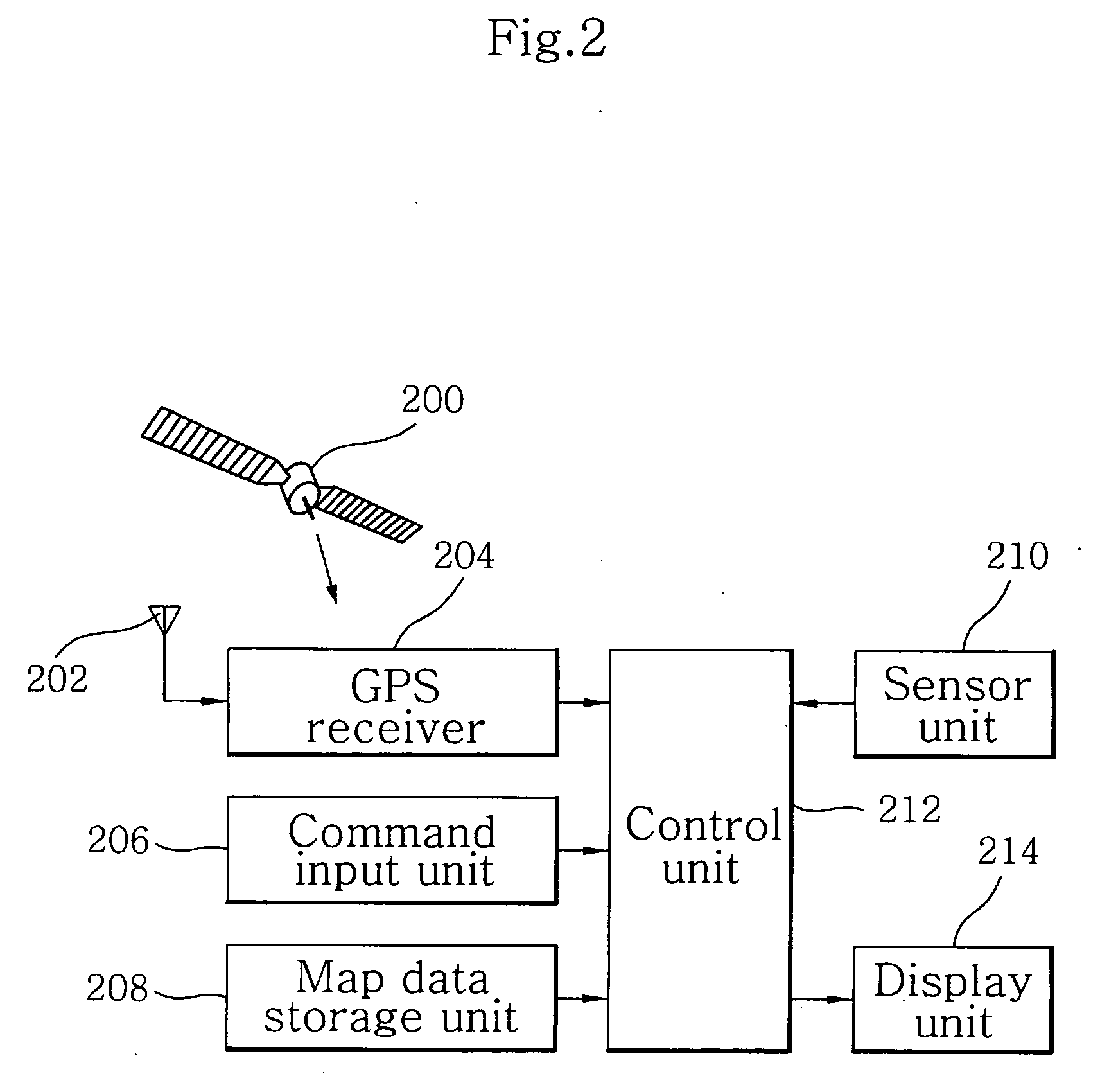
That is, since GPS detects a vehicle location using the GPS receiver that receives the navigation messages transmitted by the GPS satellites, it may not detect coordinates of a vehicle location or merely can obtain very incorrect results of detection of the coordinates at areas, including the interiors of tunnels, thickly-wooded forests or downtown areas surrounded by skyscrapers, where the GPS receiver cannot correctly receive the navigation messages transmitted by the GPS satellites.
Thus, a deduced reckoning system for deducing a vehicle location by detecting the travel distance and direction of a vehicle has been employed at areas where a vehicle location cannot be calculated since a GPS receiver cannot correctly receive navigation messages from GPS satellites.
However, the deduced reckoning system has disadvantages in that the initial location of the vehicle should be set correctly, and an estimated location of the vehicle is incorrect due to an accumulation of measurement errors inherent to the sensors if the vehicle travels for a long time during a process of deducing the vehicle location using the deduced reckoning system.
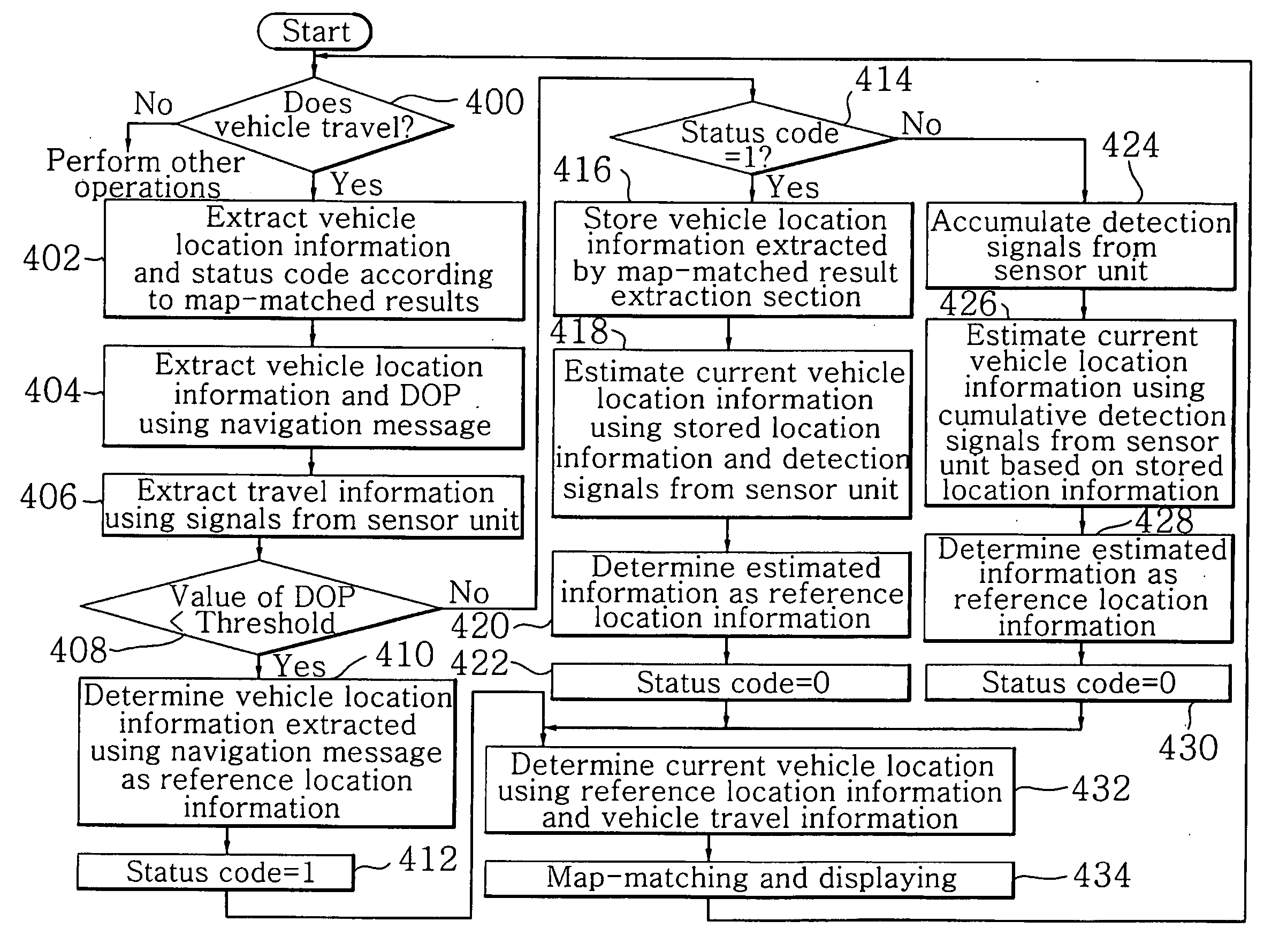
If the value of DOP is equal to or greater than 6, this cannot be utilized due to many errors in the position of the GPS receiver detected from the received navigation messages.
Thus, errors in the vehicle location detected using the detection signals from the sensors are continuously accumulated.
Accordingly, there is a problem in that the difference between an actual vehicle location and a vehicle location detected using the detection signals from the sensors increases continuously with time.
However, the detection of a vehicle location using only the detection signals from the sensors, i.e. a travel angle difference and traveled distance, contains a little error in the detected vehicle location in view of characteristics of the sensors.
Such a prior art has a problem in that since a current vehicle location is detected with respect to a just previously detected vehicle location, errors in vehicle locations detected using the detection signals from the sensors are continuously accumulated and thus the difference between an actual vehicle location and a detected vehicle location increases with time.
However, since the traveled distance of the vehicle is estimated by multiplying the number of pulse signals, which are generated from the odometer, by only the predetermined distance conversion coefficient in the prior art, a large difference occurs between an actual vehicle location and a detected vehicle location according to the travel speed of the vehicle.
Further, the travel angle difference of the vehicle detected by an output signal from the gyroscope cannot correctly reflect a 3D gradient of a road on which the vehicle travels.
Moreover, the traveled distance of the vehicle detected by the odometer cannot also reflect a fore-and-aft gradient of a road on which the vehicle travels.
These become causes of the occurrence of errors in the determination of a vehicle location, resulting in a large difference between the traveled distance and a traveled distance on a plane of an actual map.
Although there has been proposed a method using a cumulative inclinometer to reduce such errors, measurement errors are continuously accumulated in the cumulative inclinometer.
Thus, an estimated vehicle location becomes incorrect with time.
Further, at a junction of an overpass and a surface street, what road a vehicle enters or exits from cannot be correctly determined.
Therefore, there is a problem in that errors occur in performing map-matching of a vehicle location on a digital map.

Method used


Image

  • Apparatus and method for detecting vehicle location in navigation system
  • Apparatus and method for detecting vehicle location in navigation system
  • Apparatus and method for detecting vehicle location in navigation system

Examples


Embodiment Construction

[0053] Hereinafter, a method of detecting a vehicle location in a navigation system according to the present invention will be described in detail with reference to accompanying drawings.

[0054]FIG. 2 is a block diagram showing a configuration of an apparatus for detecting a vehicle location according to the present invention. As shown in the figure, the apparatus comprises a GPS receiver 204 for receiving a navigation message, which has been transmitted by a GPS satellite 200, through an antenna 202; a command input unit 206 for inputting an operation command corresponding to a user's manipulation; a map data storage unit 208 for storing a digital map data therein; a sensor unit 210, including a gyroscope, an odometer, a biaxial inclinometer for detecting lateral and longitudinal inclinations of a vehicle, and the like installed on a vehicle, to detect a travel angle difference, a traveled distance, and lateral and longitudinal inclinations of the vehicle; a control unit 212 for co...


PUM


Abstract

When a vehicle location is estimated using only detection signals from a sensor unit installed on a vehicle since the value of dilution of precision (DOP) of a navigation message received by a GPS receiver is equal to or greater than a predetermined threshold in a navigation system, the vehicle location is precisely estimated using a traveled distance, a travel angle difference, and lateral and longitudinal inclinations of the vehicle. The value of DOP of the navigation message received by the GPS receiver is compared with the predetermined threshold. If the value of DOP is less than the predetermined threshold, reference vehicle location information is set using the navigation message. If the value of DOP is equal to or greater than the predetermined threshold, the reference vehicle location information is set using vehicle location information just previously map-matched and the detection signals from the sensor unit. The vehicle location is estimated using the set reference vehicle location information and the detection signals from the sensor unit and then map-matched on a digital map stored in a map data storage unit, thereby displaying the map-matched results on a display unit.

Description

CROSS-REFERENCE TO RELATED APPLICATIONS [0001] Pursuant to 35 U.S.C. §119(a), this application claims the benefit of earlier filing date and right of priority to Korean Patent Application Nos. 10-2003-49855, 10-2003-101284, 10-2004-4477, 10-2004-28386, 28387, filed on Jul. 21, 2003, December 31, Jan. 20, 2004, 2003, Apr. 23, 2004, Apr. 24, 2004, and Apr. 24, 2004 respectively, the contents of which are hereby incorporated by reference herein in their entirety. BACKGROUND OF THE INVENTION [0002] 1. Field of the Invention [0003] The present invention relates to an apparatus and method for detecting a vehicle location in a navigation system, wherein a vehicle location can be precisely estimated using detection signals from sensors installed at a vehicle and then map-matched on a digital map so as to be displayed on a display screen. [0004] 2. Description of the Related Art [0005] As the number of vehicles such as cars continuously increases, traffic congestion becomes more critical. Pa...

Claims


Application Information

Patent Timeline
Patent Type & Authority Applications(United States)
IPC IPC(8): G01C21/30
CPCG01C21/30
Inventor LEE, HAN SUNGJUNG, MUN HOYI, DONG HOONJOE, MOON JEUNG
Owner LG ELECTRONICS INC
Why Eureka
Try Eureka