Printing sleeve with an intergrated printing surface

a printing sleeve and printing surface technology, applied in the direction of foil printing, photomechanical equipment, instruments, etc., can solve the problems of long seamexTM process, high labor intensity, and high labor intensity, and achieve excellent quality and improve the adhesion of the imageable surfa

Active Publication Date: 2005-07-14
MACDERMID PRINTING SOLUTIONS
View PDF30 Cites 14 Cited by
  • Summary
  • Abstract
  • Description
  • Claims
  • Application Information

AI Technical Summary

Benefits of technology

[0007] In accordance with this invention, a printing sleeve with an integral seamless printing surface, preferably thin walled, is provided and sequentially includes (i) a hollow cylindrical base comprised of a polymer resin, (ii) preferably, a compressible layer on the cylindrical base, (iii) a layer of photopolymerized material or other polymerized resilient material, and (iv) a layer of material having an imageable surface. It has bee

Problems solved by technology

This process works well, but is labor intensive and great care must be taken to ensure that the registration of the plate on the cylinder is accurate.
Problems arise with this process, however, in trying to eliminate the seam caused by the joining of the ends of the flat printing plate.
Additionally, the SEAMEX™ process is long and labor intensive.
Degradation of image fidelity may also result due to heat history the photopolymer is subjected to.
It is believed, however, tha

Method used


Image

  • Printing sleeve with an intergrated printing surface
  • Printing sleeve with an intergrated printing surface

Examples


example i

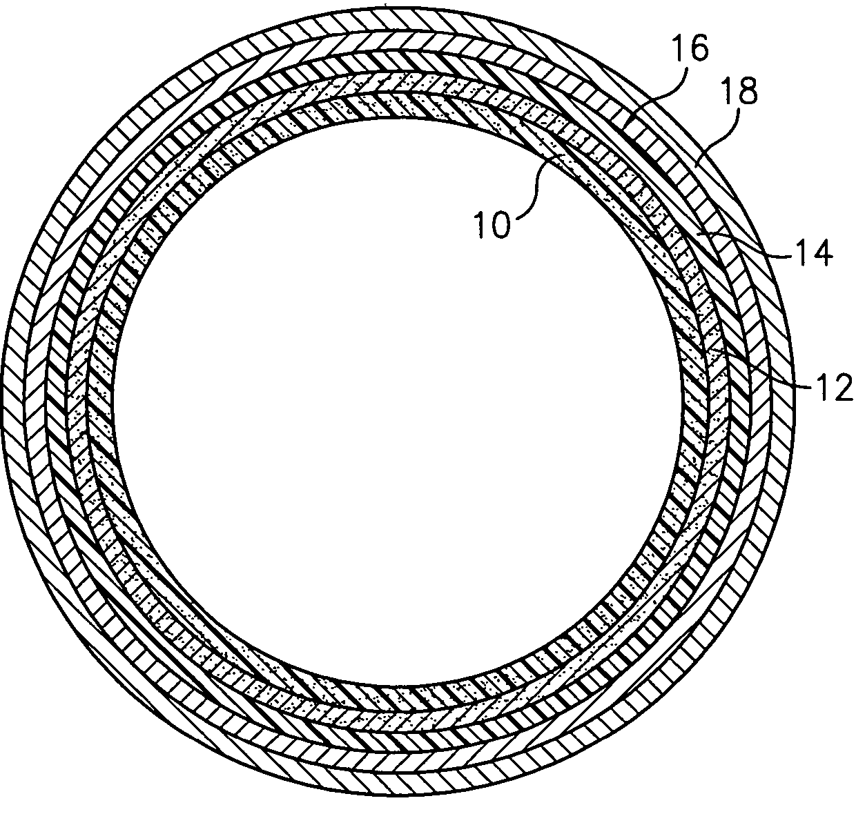
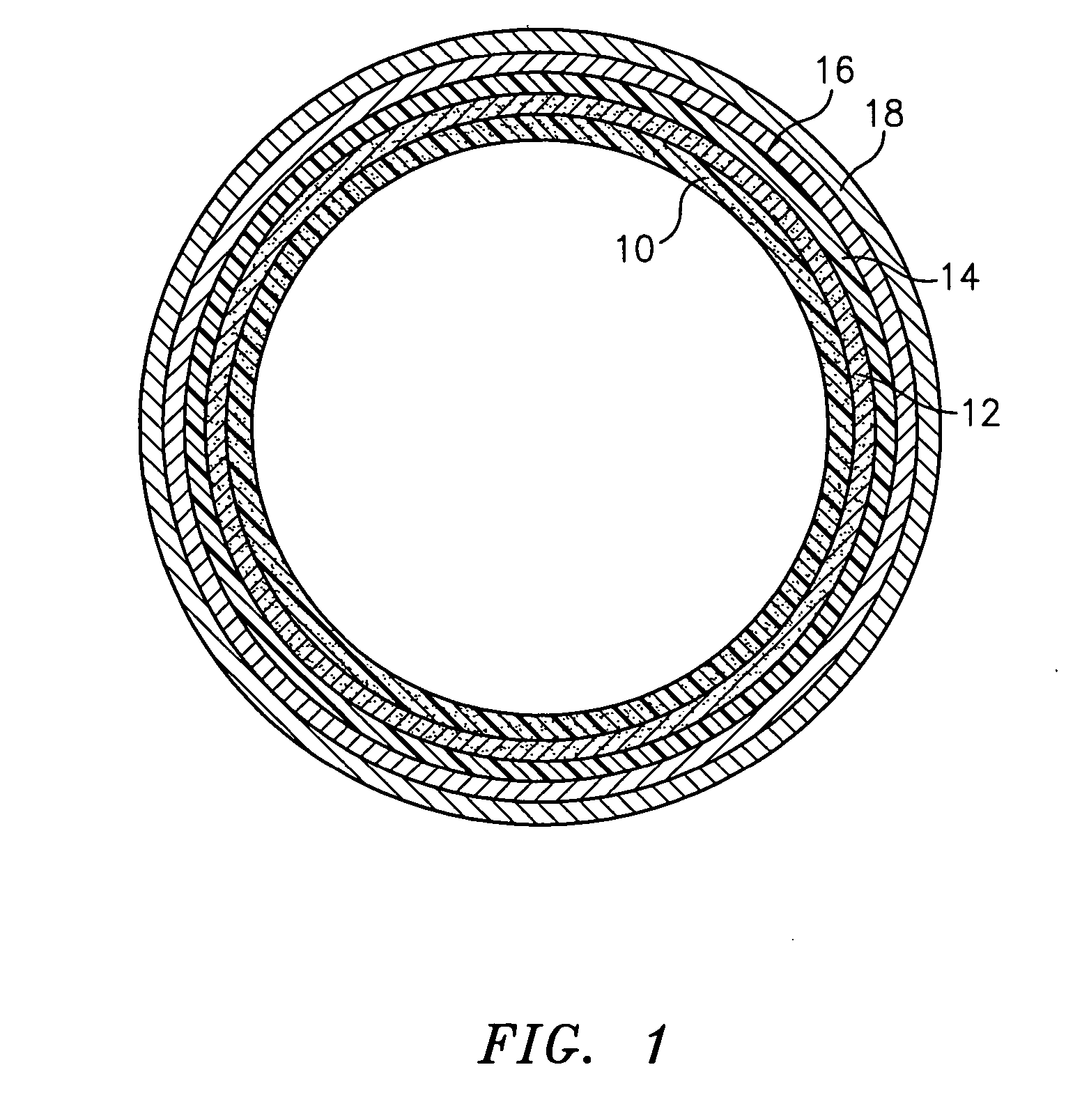
[0042] The mandrel is inspected for imperfections or defects and thoroughly cleaned. A mold release is applied to the mandrel and pre-heated to 100° to 120° F. The epoxy resin and hardener (Ratio approximately 3.3:1) is mixed by hand for 1-2 minutes until it thickens. This resin-hardener mixture is then applied to the mandrel. Type 106-glass fabric pre-cut into 4-inch width is then wrapped around mandrel to be sure that the fabric is totally wetted out. The polymer-glass composite is then allowed to crosslink or gel by applying heat for about 30 minutes. The sleeve is removed from the mandrel while the sleeve and mandrel are still hot by introducing compressed air between the sleeve and mandrel to assist with the removal. The sleeve is then baked for 4 hours at 120° F. After the baking step the sleeve is further machined or ground to the specified gage (16+ / −½ mil wall thickness).

[0043] A floor layer (Table I) is first extruded onto either of the hollow cylindrical base. The floor ...


PUM

PropertyMeasurementUnit
Fractionaaaaaaaaaa
Fractionaaaaaaaaaa
Pressureaaaaaaaaaa

Abstract

A seamless printing sleeve comprising a hollow cylindrical base and a seamless imageable surface as its outermost layer is described. The imageable surface acts as an integral flexographic printing surface. Preferably the printing sleeve comprises an intermediate photopolymer or resilient polymer layer between the outer surface of the base and the imageable surface. Also, preferably the base is uniformly transparent or translucent to actinic radiation.

Description

FIELD OF THE INVENTION [0001] The invention reveals a cylindrically shaped printing sleeve which is readily axially mountable and dismountable from a complimentary printing cylinder, which printing sleeve has an integral imageable surface thereon. BACKGROUND OF THE INVENTION [0002] Historically, in flexographic printing, flat, flexible printing plates, fabricated from photopolymers, were hand mounted onto print cylinders by wrapping the printing plate around the cylinder and adhering it there with using various methods such as clamps, tape, magnets or other similar devices. This process works well, but is labor intensive and great care must be taken to ensure that the registration of the plate on the cylinder is accurate. Typically, a compressible material is inserted between the print cylinder and the printing plate to allow for additional compression during the print process. [0003] In the context of the foregoing printing process, cylindrical printing sleeves could be used to inc...

Claims


Application Information

Patent Timeline
IPC IPC(8): B41N1/00B41N1/12B41N1/22
CPCG03F7/18B41N6/00
Inventor KANGA, RUSTOM S.BORSKI, MARK A.JANSSEN, PATRICIA I.
Owner MACDERMID PRINTING SOLUTIONS
Why Eureka
Try Eureka