Apparatus and method for electrofriction welding

a technology of electric friction welding and apparatus, applied in the field of electric friction welding apparatus, can solve the problems of haz, high undesirable haz, and increased time of weld heat-affected zone, and the relative motion of the contact surface in the weld zone is typically slow

Active Publication Date: 2005-07-14
GENERAL ELECTRIC CO
View PDF5 Cites 34 Cited by
  • Summary
  • Abstract
  • Description
  • Claims
  • Application Information

AI Technical Summary

Benefits of technology

[0009] At least one exemplary embodiment of the present invention provides an apparatus for electrofriction welding of a consumable material onto a surface of a base material including a contact element; a contact element housing, the contact housing arranged and configured to hold the contact element, selectively move the contact element in a plane substantially parallel to the surface, selectively force a working surface of the contact element against the surface in a weld zone with a contact force, the contact force being applied in a direction substantially normal to the surface, wherein the working surface of the contact element moves under a force applied in the direction of motion while in contact with the surface to generate frictional heating; an electrode; and an electrical power supply, the electrical power supply being connected to the electrode and arranged to produce an electric current into the base material in the region of the weld zone; wherein the electric current causes resistance heating of the weld zone, and further wherein the combination of frictional heating, resistance heating and contact force is sufficient to cause semi-solid state welding of the consumable material onto the weld zone. An apparatus for the electrofriction welding of a consumable material may also include one or more supplemental heating elements arranged in close proximity to the contact element for the preheating of the weld zone, further wherein the combination of preheating, frictional heating, resistance heating and contact force is sufficient to cause semi-solid state welding of the consumable material onto the weld zone.

Problems solved by technology

The relative motion of the contacting surfaces in the weld zone is typically slow, and, as a result, a large fraction of the heat generated is lost during the welding process, i.e., by thermal conduction into the base metal(s), consumable filler material and / or non-consumable probe.
The corresponding broadening of the width, increase in the time, and increase in temperature of the weld heat-affected zone (HAZ) can be highly undesirable, particularly for materials that are susceptible to chemical dilution, thermal sensitization or helium embrittlement.
Such thermal inefficiency also increases the power required to deposit a desired bead.
In addition, the size and weight of the tooling required to apply the necessary normal forces and vibratory motion and / or torque will tend to be substantial.
Due to the lack of relative motion between the mating surfaces, resistance welding typically provides no significant cleaning action of the mating surfaces and does not tend to produce a well homogenized material in the weld zone.
Because of the high applied forces required by these conventional welding processes, the tooling to apply them is correspondingly large and heavy and generally inappropriate for remotely-applied welds in limited-access areas where a semi-solid state weld may be required.
A simplistic “scaling” approach for developing tools for confined spaces will tend to result in tooling of a size which is impractical or impossible to use for remote field applications in limited access areas.
For example, tooling of size and strength sufficient to provide satisfactory weld size and productivity will tend to be too large to operate in confined areas.
Conversely, tooling that has been reduced in size to a degree sufficient to operate in confined areas will tend to exhibit weld size and productivity that are undesirable or unacceptable for meeting “critical path schedules.”
However, no apparatus or method heretofore has been known to overcome the problems of either conventional resistance or friction semi-solid state welding with respect to production of weld joints or application of weld cladding in remote and / or confined locations where process tooling and delivery equipment size, weight, and reaction force values must be kept to a minimum, while also providing high productivity and high weld quality.

Method used


Image

  • Apparatus and method for electrofriction welding
  • Apparatus and method for electrofriction welding
  • Apparatus and method for electrofriction welding

Examples


Embodiment Construction

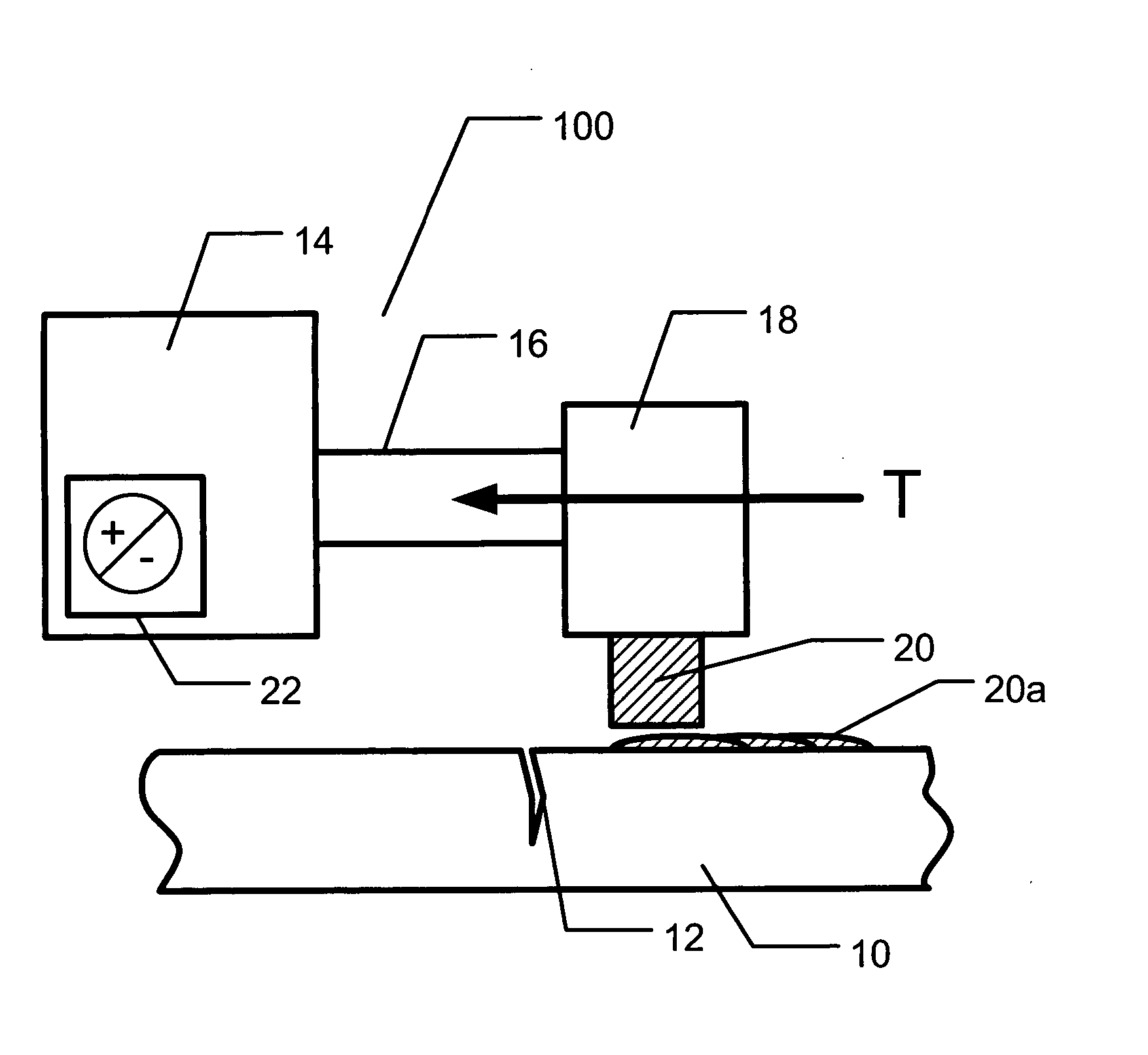
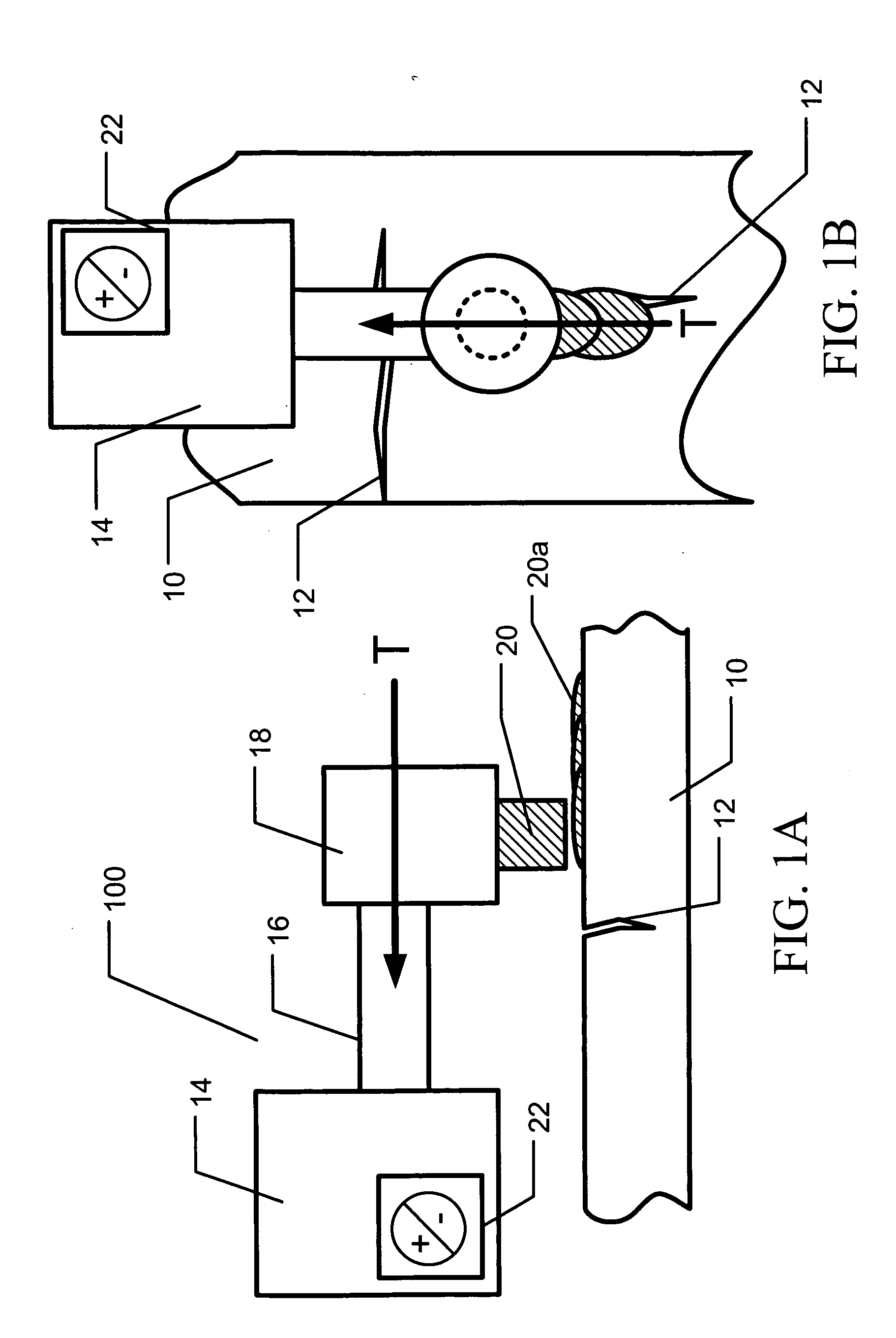
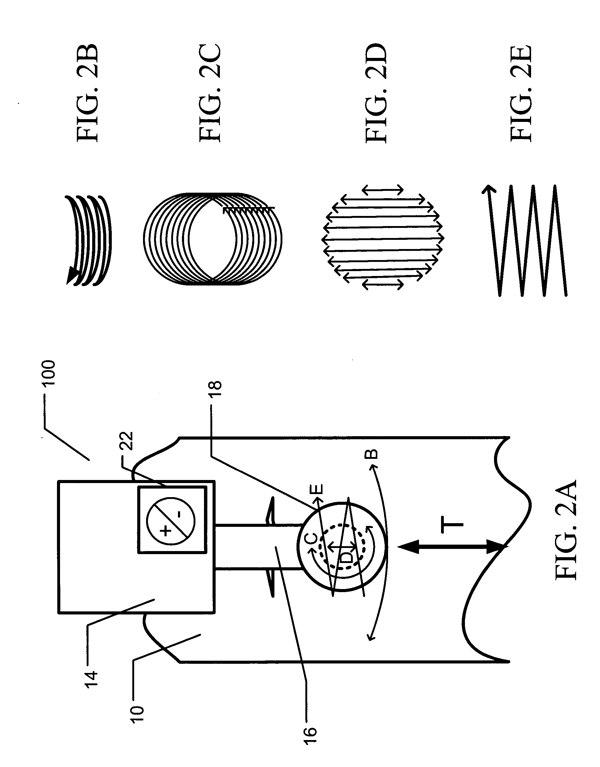
[0025] Exemplary embodiments of the invention provide an apparatus for applying a combination of electrical resistance heating and mechanical friction heating at the same time and location or at substantially at the same time and place, to produce heating sufficient to support solid state or semi-solid state welding. By utilizing a combination of heating modes, the exemplary embodiments of the apparatus may achieve synergistic heating that may provide improved welding efficiency, improved welding productivity and / or tooling of a scale suitable for operation in remote and / or confined locations. This simultaneous application (e.g., combination) of electrical resistance and mechanical friction heating modes to apply the necessary heating to support welding will be referred to herein as “electrofriction welding”

[0026] Electrofriction welding uses both mechanical friction heating and electrical resistance heating simultaneously, or substantially simultaneously, to heat and forge base met...


PUM

PropertyMeasurementUnit
contact forceaaaaaaaaaa
resistanceaaaaaaaaaa
dimensionaaaaaaaaaa

Abstract

An apparatus and method arranged to use a combination of at least electrical resistance heating and mechanical friction heating to case a base material and/or a consumable material to reach a combination of temperature and pressure sufficient to cause welding. The method and apparatus configured for the simultaneous or substantially simultaneous application of both electrical resistance heating and friction heating to achieve welding is referred to as an electrofriction process, method or apparatus. This combination of resistance and friction heating allows the heating to be more localized within a relatively small weld zone, thereby improving the efficiency of the overall process and allowing the size, weight and strength and/or the cost of the application equipment and/or associated fixtures and power supplies to be reduced while enhancing its capability for operation in confined spaces and providing satisfactory welding performance.

Description

TECHNICAL FIELD AND INDUSTRIAL APPLICABILITY OF THE INVENTION [0001] The present invention relates generally to welding, and more particularly to an apparatus and a method for solid state or semi-solid state welding that utilizes a combination of electrical resistance and mechanical friction to achieve the heating necessary for welding. BACKGROUND OF THE INVENTION [0002] Conventional friction welding relies on very high magnitude applied forces and mechanical torques, or, alternatively, lateral vibratory forces, to produce the desired hot forging temperature and pressure conditions within a weld zone. The relative motion of the contacting surfaces in the weld zone is typically slow, and, as a result, a large fraction of the heat generated is lost during the welding process, i.e., by thermal conduction into the base metal(s), consumable filler material and / or non-consumable probe. The corresponding broadening of the width, increase in the time, and increase in temperature of the weld...

Claims


Application Information

Patent Timeline
Patent Type & Authority Applications(United States)
IPC IPC(8): B23K11/11B23K20/10
CPCB23K20/10B23K11/11
Inventor OFFER, HENRY PETER
Owner GENERAL ELECTRIC CO
Why Eureka
Try Eureka