Cooling system for hot parts of an aircraft engine, and aircraft engine equipped with such a cooling system

a technology for aircraft engines and cooling systems, which is applied in the direction of machines/engines, lighting and heating apparatus, and engine maintenance, etc., can solve the problems of inoperable heat exchangers, difficult access to engine maintenance parts, and difficulty in recirculating air in the heat exchangers, so as to eliminate the risk of recirculation of air increase the pressure loss in the heat exchanger.

Inactive Publication Date: 2005-07-14
SNECMA MOTEURS SA
View PDF10 Cites 44 Cited by
  • Summary
  • Abstract
  • Description
  • Claims
  • Application Information

AI Technical Summary

Benefits of technology

[0027] According to the invention, the outlet from the evacuation pipe of each channel opens up at the outlet from the nacelle ejection nozzle, or beyond it on the downstream side. Thus, air that exits from the evacuation pipe is at atmospheric pressure. Consequently, the risk of recirculation of air in the heat exchanger is eliminated, and pressure losses in the heat exchanger are increased.

Problems solved by technology

A first disadvantage is related to engine maintenance, particularly of the gas generator.
In the presence of a cooling system according to prior art, and particularly if the casing is in position around the gas generator or a channel fixed to the nacelle, it becomes difficult to access some parts of the engine for maintenance.
A second disadvantage of systems according to prior art is due to the fact that colder air used to cool fluid circulating in the heat exchanger is restored on the downstream side inside the fan duct.
There is then a risk that air could circulate in the inverse direction or not circulate at all, which would make the heat exchanger inoperative.

Method used


Image

  • Cooling system for hot parts of an aircraft engine, and aircraft engine equipped with such a cooling system
  • Cooling system for hot parts of an aircraft engine, and aircraft engine equipped with such a cooling system
  • Cooling system for hot parts of an aircraft engine, and aircraft engine equipped with such a cooling system

Examples


Embodiment Construction

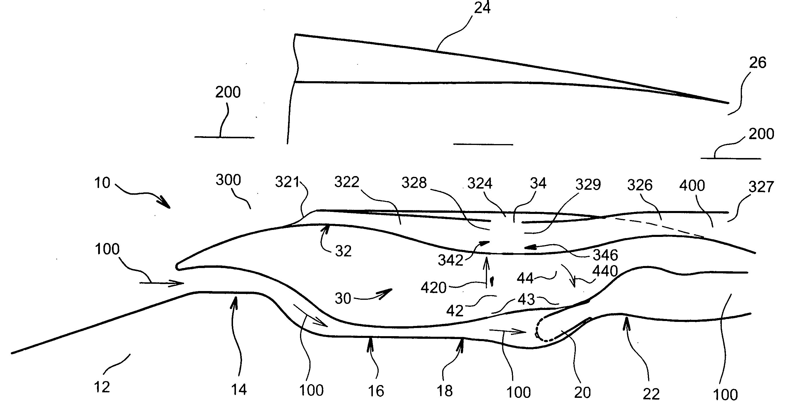
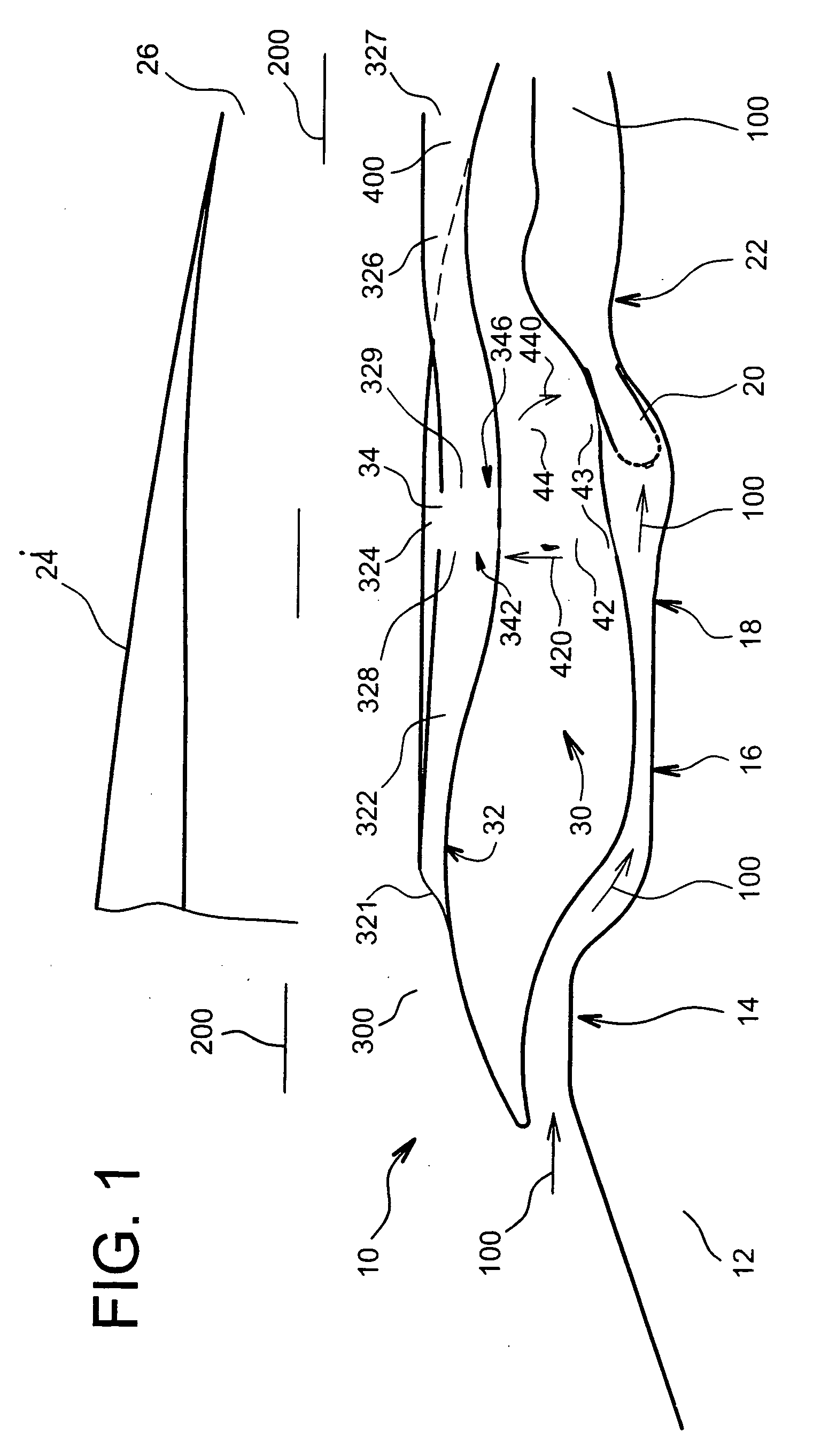
[0037]FIG. 1 diagrammatically shows an aircraft engine 10 with an axis of revolution 12.

[0038] In a manner known per se, the aircraft engine 10 comprises low pressure compressor stages 14, medium pressure compressor stages 16, high pressure compressor stages 18, a combustion chamber 20 and turbines 22. The aircraft engine 10 is surrounded by a nacelle 24 that terminates with an ejection nozzle 26.

[0039] In a manner known per se, a primary air flow represented by arrows 100 circulates inside the engine 10. It is heated as it passes through the compressor stages 14, 16 and 18 before arriving at the turbines 22.

[0040] In a manner known per se, a secondary air flow represented by the arrows 200 circulates in the nacelle 24 around the engine 10. This secondary air 200 external to the engine 10 is colder than the primary air 100 inside the engine 10.

[0041] According to the invention, the engine 10 comprises a cooling system 30 designed to cool hot parts of the engine 10, for example s...


PUM


Abstract

The cooling system (30) for an aircraft engine (10) comprises a channel (32) that draws off cold air in the secondary air flow (200), and a heat exchanger (34) located in the channel (32) and in which hot air circulates.
The channel (32) comprises:
    • a supply pipe (322) and an evacuation pipe (326) fixed to the nacelle (324),
    • an intermediate box (324) located between the supply pipe (322) and the evacuation pipe (326), fixed to the engine (10), and in which the heat exchanger (34) is placed.
Application to cooling of hot parts (22) in an aircraft engine (10).

Description

TECHNICAL DOMAIN [0003] This invention relates to the technical field of cooling systems for hot parts of aircraft engines. [0004] More particularly it relates to a cooling system comprising a set of heat exchangers, to cool hot parts of an aircraft engine such as high pressure turbine blades in this aircraft engine. [0005] It also relates to an aircraft engine equipped with such a cooling system. STATE OF PRIOR ART [0006] It is known that heat exchangers can be installed in an aircraft engine to cool hot parts of an aircraft engine. [0007] Document FR 2 400 618 discloses a turbo-fan type of aircraft engine using an air / air type cooling system, and an associated cooling method. Hot parts such as fixed and mobile blades of the high pressure turbine are cooled by cooling air originating from part of the primary air drawn off at the outlet from the compressor or between compressor stages. This air cooling hot parts is itself firstly cooled before passing over the parts to be cooled, by...

Claims


Application Information

Patent Timeline
Patent Type & Authority Applications(United States)
IPC IPC(8): F02K1/78F02C7/141F02K1/38F02K3/02F28D21/00
CPCF02C7/141F02K3/02F28D21/0014F05D2260/208Y02T50/671Y02T50/676F28D2021/0021Y02T50/60
Inventor BEUTIN, BRUNOMAZEAUD, GEORGESPALMISANO, LAURENTFONQUERNE, VINCENTYVON, DIDIER
Owner SNECMA MOTEURS SA
Why Eureka
Try Eureka