High altitude reconnaissance vehicle

a reconnaissance vehicle and high-altitude technology, applied in the direction of launching/towing gear, wireless commuication services, energy-efficient board measures, etc., can solve the problems of 50 watts of power, system exposed, and failure to successfully fly under propeller power for station-keeping

Active Publication Date: 2005-07-14
THE JOHN HOPKINS UNIV SCHOOL OF MEDICINE
View PDF22 Cites 20 Cited by
  • Summary
  • Abstract
  • Description
  • Claims
  • Application Information

AI Technical Summary

Benefits of technology

[0010] In accordance with the present invention, an airship deployment system is provided comprising (a) an airship capable of remote control, comprising (i) an inflatable body having a shape to achieve laminar flow; (ii) at least one propeller assembly for station keeping and repositioning said airship and capable of being folded into a compacted position and unfolded into an operational position; and (iii) a payload comprising at least one of a chemically generated and compressed gas for inflating said inflatable body; and means for transferring data between said airship and at least one remote location; and (b) a missile for carrying said airship in a deflated and folded state to a predetermined location and predetermined altitude and releasing said airship at said predetermined location and said predetermined altitude, wherein when said airship is released from said missile said inflatable body is inflated and said at least one propeller assembly is unfolded into said operational position.
[0011] Further in accordance with the present invention, a method of deploying an airship having an inflatable body, an airship payload and at least one folding propeller assembly is provided comprising the steps of packaging said airship for high altitude deployment as a missile payload; transporting said airship to a predetermined location and a predetermined altitude as said missile payload; releasing said airship from said missile payload; and deploying said airship at said predetermined location and predetermined altitude.

Problems solved by technology

Among these factors are ease of deployment, time required to deploy, altitude requirements, environmental factors the systems are exposed to during both initial deployment and final location, costs, and especially in military applications, vulnerability to ground attack.
Finally, NSMVs can ascend to about 120,000 ft, have a range of about 200 nautical miles, can station-keep for about 5 days, can carry a payload of about 100 lbs., consume about 50 Watts of power, but have not successfully flown under propeller power for station-keeping.
UAVs are also vulnerable to air defenses due to their low altitude and can be grounded by bad weather.
ULDBs also have problems.
Without propulsion, the ULDBs are unable to station-keep and depend on wind direction for movement.
Satellites have a different set of problems.
The lead-time for new satellites is many years, making new satellites unavailable to support short-term needs.
Some of the additional disadvantages associated with present atmospheric based systems include the following.
Winged aircraft and most lighter-than-air airships, or tethered aerostats are limited to the lower altitudes with denser atmosphere, thereby limiting their horizon coverage.
Further, they require substantial support and are not generally on station for long periods (days or months) due to crew limits, weather vulnerability, and / or equipment reliability.
Satellites are expensive to deploy and, although their horizon coverage is great, their distance to the objects of surveillance, and communications relays, combined with on-board power constraints limit resolution, detectibility, and communications bandwidth.
Also, a single satellite cannot provide continuous reconnaissance because a platform in low-earth orbit passes outside of the field of view of a target within about ten minutes and does not return for at least one orbit period of about 90 minutes.
A geosynchronous-orbit satellite could in theory provide continuous reconnaissance but at enormous cost because of the expensive sensors required for the very long distance to geosynchronous orbit (over 22,000 miles).
A constellation of low-earth-orbit satellites could also provide continuous reconnaissance but again at enormous cost because of the significant number of satellites required.

Method used


Image

  • High altitude reconnaissance vehicle
  • High altitude reconnaissance vehicle
  • High altitude reconnaissance vehicle

Examples


Embodiment Construction

[0019] Preferred embodiments of the present invention will be described herein below with reference to the accompanying drawings, wherein the same components or parts thereof will be represented with the same reference numerals or symbols to avoid any redundancy or repetition. In the following description, well-known functions or constructions are not described in detail since they would obscure the invention in unnecessary detail.

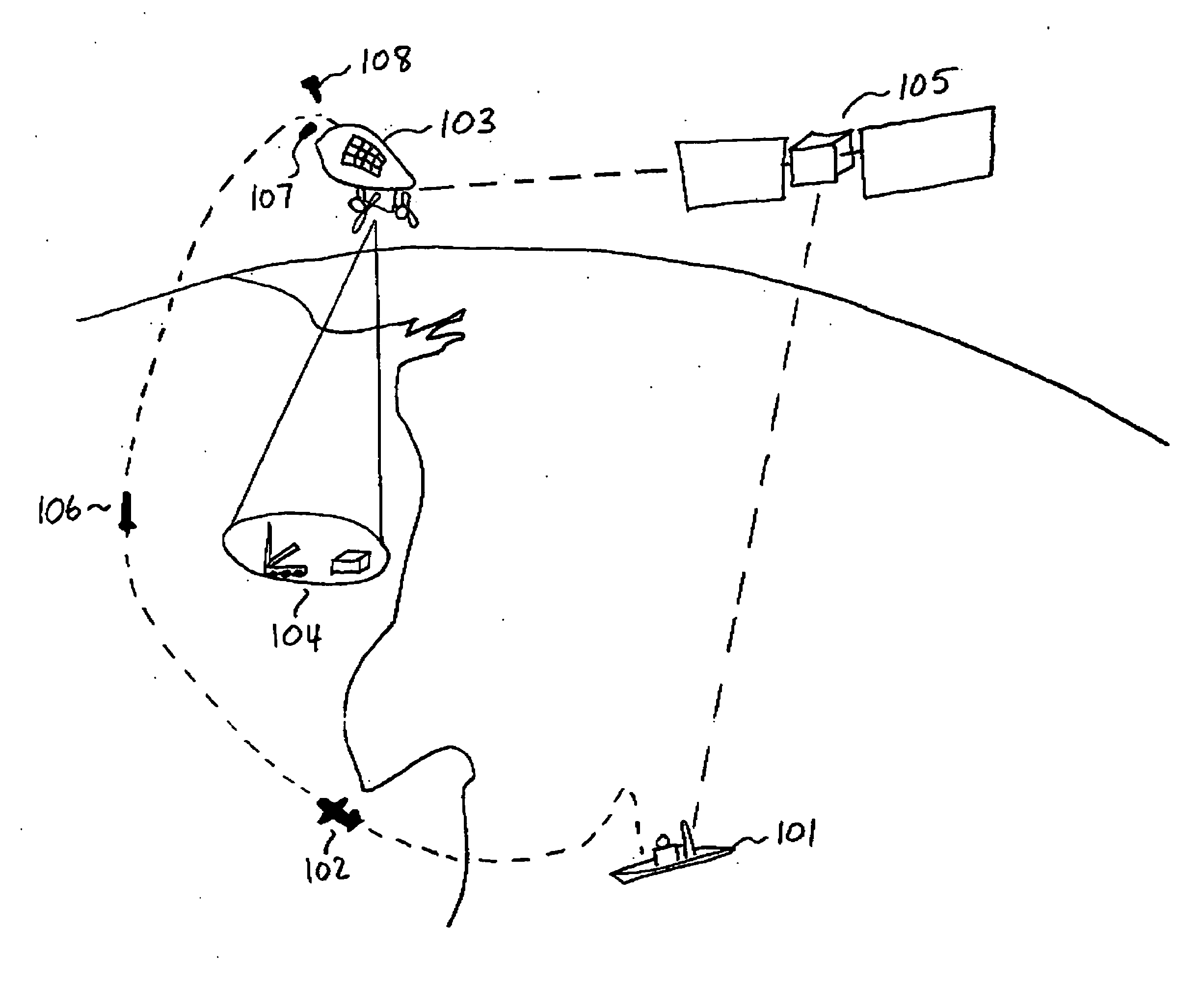
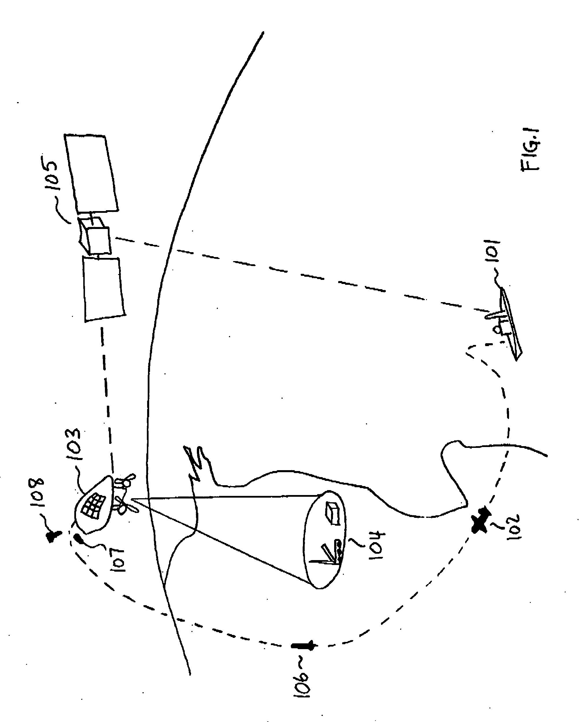
[0020] In general, many recognize the need for a long-duration, stable platform for reconnaissance and communications. A near-space platform occupies a niche between a UAV and a satellite. This type of platform shares the availability, ability to reconfigure, low-cost and rapid launch benefits of UAVs while having the ability to station-keep for extended periods, and provide a general invulnerability associated with high altitude satellites.

[0021] The novel, station keeping stratospheric vehicle (station-keeping inflatable platform or “HARVe” as used her...


PUM


Abstract

An airship deployment system comprises an airship of unique shape having laminar flow over this shape to enable low power propulsion, capable remote control, comprising an inflatable body; a propeller assembly for station keeping and repositioning said airship and capable of being folded into a compacted position and unfolded into an operational position; and a payload, comprising gas for inflating said inflatable body; and means for transferring data between said airship and a remote location; and a missile for carrying said airship in a compacted state to a predetermined location and altitude, and releasing said airship at said predetermined location and altitude. When said airship is released from said missile said inflatable body is inflated and said propeller assembly is unfolded into said operational position.

Description

CROSS REFERENCE TO RELATED APPLICATIONS [0001] This application claims priority to U.S. Provisional Application No. 60 / 487,746, filed Jul. 16, 2003, and U.S. Provisional Application No. 60 / 549,433, filed Mar. 2, 2004, the contents of each of which are incorporated herein by reference.BACKGROUND OF THE INVENTION [0002] 1. Field of the Invention [0003] The present invention relates generally to a system and method for a high altitude reconnaissance vehicle (HARVe). [0004] 2. Description of the Related Art [0005] Whether for military or civilian use, atmospheric based vehicles or stations are becoming more commonplace in a society requiring real-time communications and information to be supplied over greater distances. Systems placed in low, medium and high altitude locations include weather balloons, satellites used for reconnaissance or communications, and systems for environmental analysis, to name a few. The existing atmospheric based systems include sensing devices from infrared (...

Claims


Application Information

Patent Timeline
Patent Type & Authority Applications(United States)
IPC IPC(8): B64B1/02B64B1/06B64B1/24B64C11/28B64D5/00B64D27/24
CPCB64B1/02B64B1/24B64C11/28B64D5/00Y02T50/69B64D2211/00Y02T50/44Y02T50/62B64D27/24Y02T50/40Y02T50/50Y02T50/60
Inventor KRILL, JERRY A.ROTH, MICHAEL W.RIEDEL, FREDERICK W.FEINSTEIN, MATTHEW R.MASON, WILLIAM T. IIIDARRIN, MARGARET ANNSZCZEPANOWSKI, RAFAL P.NERADKA, VINCENT F.
Owner THE JOHN HOPKINS UNIV SCHOOL OF MEDICINE
Why Eureka
Try Eureka