Eureka AIR delivers breakthrough ideas for toughest innovation challenges, trusted by R&D personnel around the world.

Electrically pressurized on-board inert gas generation system

a gas generation system and inert gas technology, applied in the direction of fuel supply for power plants, fuel tank safety measures, aircraft power plants, etc., can solve the problems of downstream components being damaged, the temperature of air becomes so high, and the thin walls cannot support very much differential pressure between inside and outsid

Inactive Publication Date: 2005-07-14
PARKER HANNIFIN CORP
View PDF10 Cites 22 Cited by
  • Summary
  • Abstract
  • Description
  • Claims
  • Application Information

AI Technical Summary

Benefits of technology

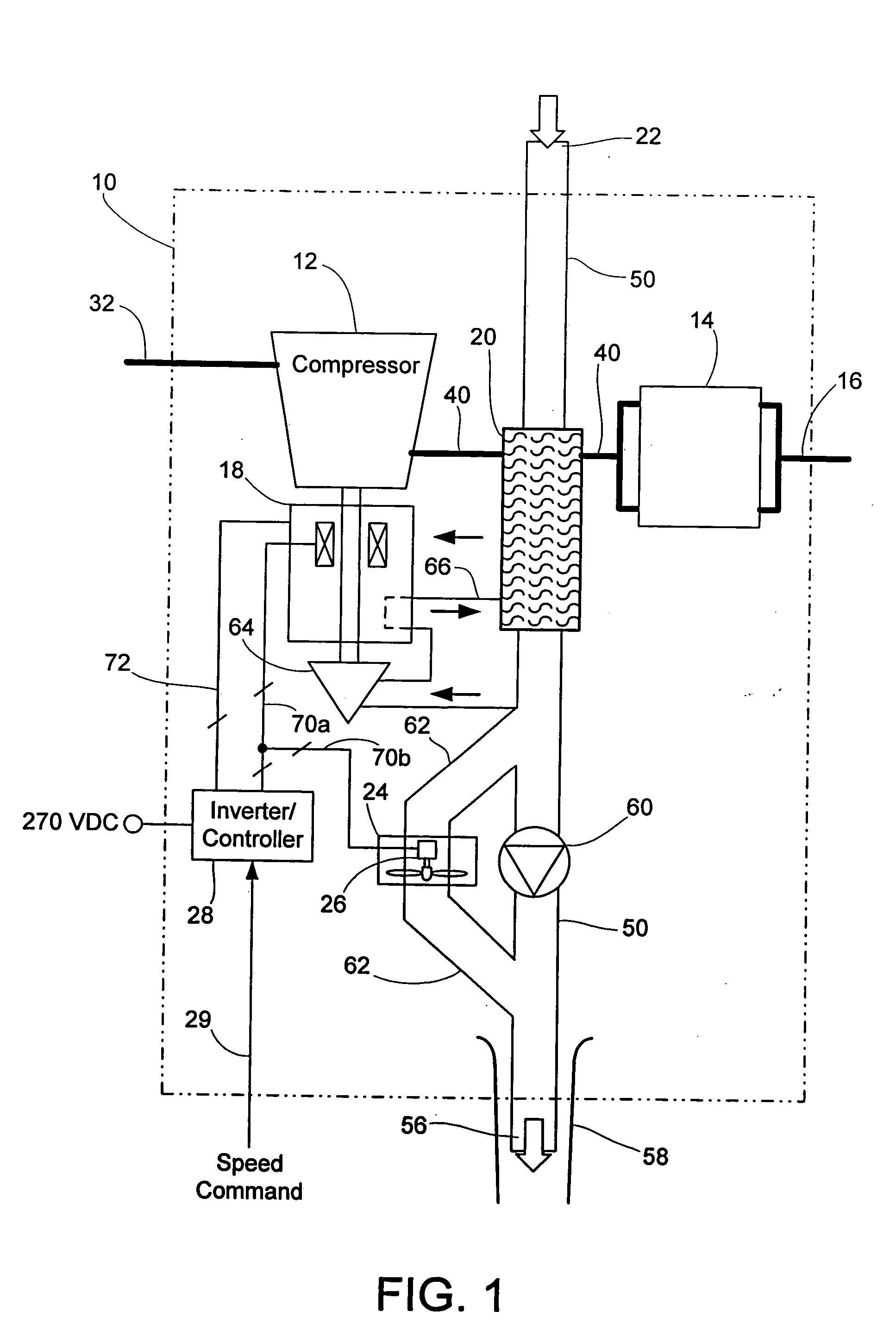
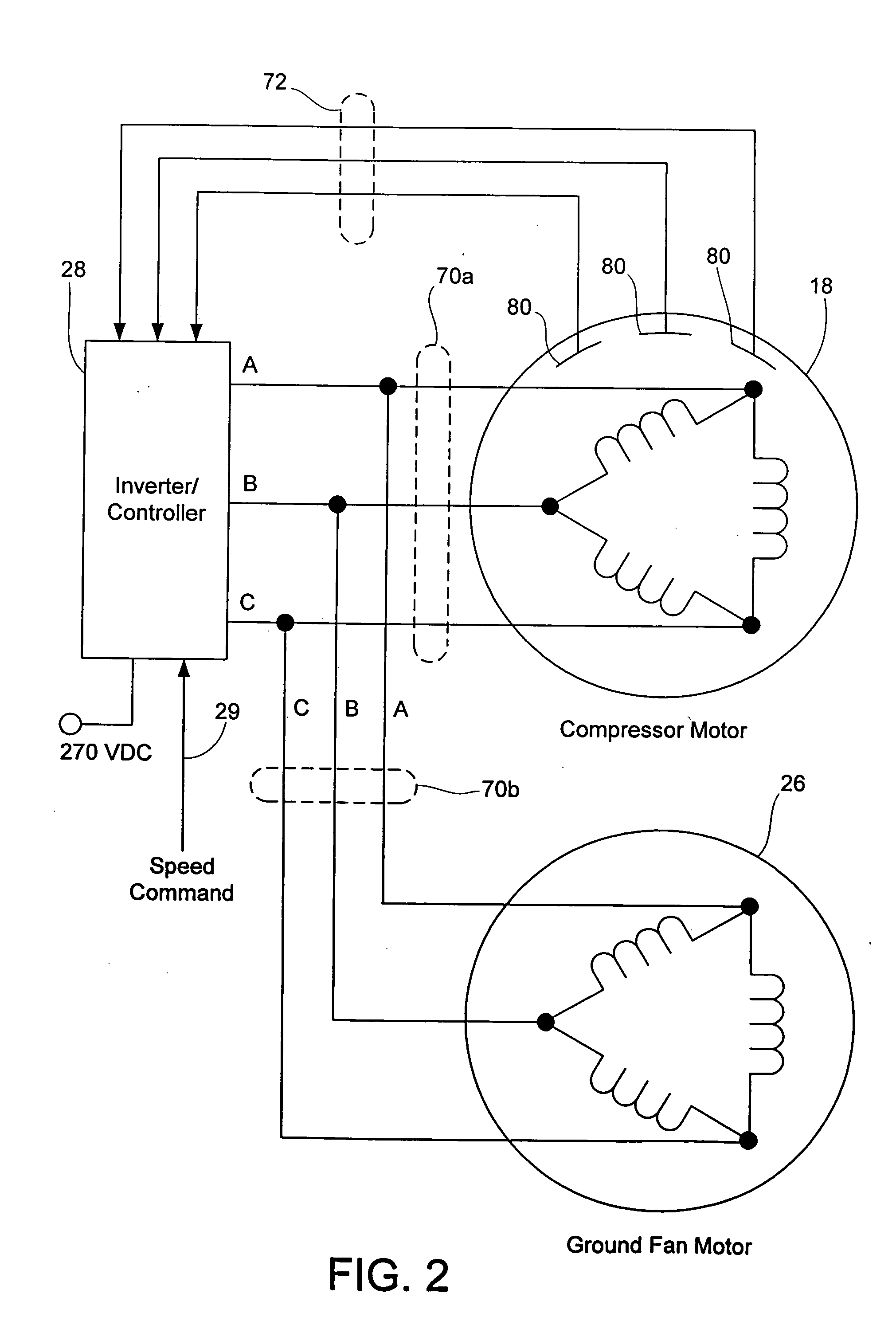
[0009] According to one aspect of the invention, an on-board inert gas generation system is provided. The system provides inert gas to a fuel tank of an aircraft and includes an air compressor for providing a supply of compressed air, the air compressor being driven by a compressor motor. The system further includes a separator for separating the inert gas from the compressed air provided by the air compressor, the inert gas being substantially oxygen depleted. In addition, the system includes an output for delivering the inert gas from the separator to the fuel tank, and a ground fan for providing air flow to cool the compressed air prior to the compressed air being separated by the separator, the ground fan being driven by a ground fan motor. Still further, the system includes an inverter/controller circuit for providing controlled electrical power to the compressor motor to control at least one of speed and torque of the compressor motor based on feedback provided

Problems solved by technology

Such thin walls cannot support very much differential pressure between inside and outside as the fuel volume varies and, hence, must have a variable amount of gas to make up for the unfilled fuel volume and equalize the pressure.
Compressing air to pass through the separator causes the air to heat up, and the temperature of the air becomes so great that downstream components could be damaged.
Unfortunately, there have been disadvantages associated with OBIGGS utilizing ground fans for providing air flow to cool the compressed air.
Minimum cost, size, and weight of the motor and fan would probably lead to selection of 28 vdc brush motors, but these require additional components, e.g., filters, to avoid electrical interference and are unquestionably the least reliable and possibly the heaviest systems because of the filter components.
Such brushless motors can be both heavy and expensive.

Method used


Image

  • Electrically pressurized on-board inert gas generation system
  • Electrically pressurized on-board inert gas generation system
  • Electrically pressurized on-board inert gas generation system

Examples


Embodiment Construction

[0014] The present invention will now be described with reference to the drawings, wherein like reference numerals are used to refer to like elements throughout.

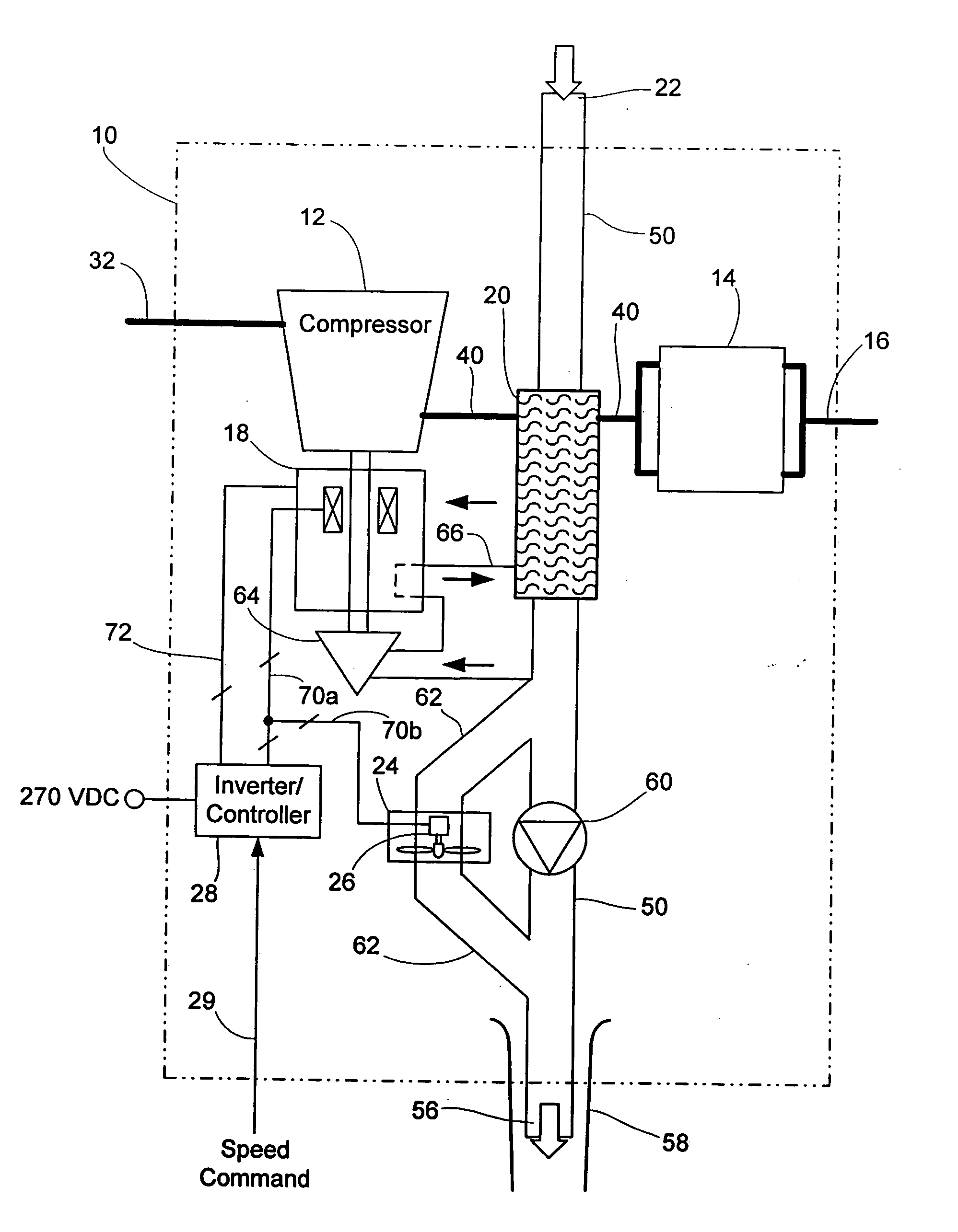
[0015] Referring initially to FIG. 1, an on-board inert gas generation system (OBIGGS) 10 is shown in accordance with the present invention. The relevant components of the OBIGGS 10 include an air compressor 12 that provides compressed air to a separator 14. The separator 14 separates the compressed air into nitrogen enriched (or oxygen depleted) air and oxygen enriched air. The nitrogen enriched air becomes the fill gas and is provided via an output 16 to the aircraft fuel tank(s) (not shown). The compressor 12 is driven by a motor 18 designed to provide sufficient horsepower and torque to compress the air provided to the separator 14.

[0016] The OBIGGS 10 further includes a heat exchanger 20 that serves to cool the compressed air provided by the compressor 12 prior to being delivered to the separator 14. The heat exchange...


PUM


Abstract

An on-board inert gas generation system that provides inert gas to a fuel tank of an aircraft. The system includes an air compressor for providing a supply of compressed air, the air compressor being driven by a compressor motor. The system further includes a separator for separating the inert gas from the compressed air provided by the air compressor, the inert gas being substantially oxygen depleted. In addition, the system includes an output for delivering the inert gas from the separator to the fuel tank, and a ground fan for providing air flow to cool the compressed air prior to the compressed air being separated by the separator, the ground fan being driven by a ground fan motor. Still further, the system includes an inverter / controller circuit for providing controlled electrical power to the compressor motor to control at least one of speed and torque of the compressor motor based on feedback provided from the compressor motor, and also providing the controlled electrical power to drive the ground fan motor.

Description

[0001] This application claims priority under 35 U.S.C. §119 to U.S. Provisional Application No. 60 / 531,007, filed Dec. 18, 2003, the contents of which are hereby incorporated by reference.TECHNICAL FIELD [0002] The present invention relates generally to fuel tank inerting systems. More particularly, the present invention relates to an on-board inert gas generation system (OBIGGS) wherein a nitrogen enriched, oxygen depleted stream is produced by an electrically pressurized air separation module. BACKGROUND OF THE INVENTION [0003] Aircraft fuel tanks consist of thin walled shells that hold continuously varying amounts of jet fuel. The walls are thin to limit the weight of aircraft components. Such thin walls cannot support very much differential pressure between inside and outside as the fuel volume varies and, hence, must have a variable amount of gas to make up for the unfilled fuel volume and equalize the pressure. This fill gas must be “inert” so that accidental sparks from elec...

Claims


Application Information

Patent Timeline
IPC IPC(8): B01J19/14B64D37/00B64D37/32
CPCB64D37/32B01J19/14
Inventor STEVENS, CURTIS EDGAR
Owner PARKER HANNIFIN CORP
Why Eureka
Eureka Blog
Learn More