
Measuring device having a plurality of potentiometric electrode pairs situated on a substrate

a technology of potentiometric electrodes and measuring devices, which is applied in the direction of measurement devices, instruments, material electrochemical variables, etc., can solve the problems of disadvantageous high equipment costs for process checking and process tracking, large number of parallel reactors, and high degree of measurement complexity. , to achieve the effect of reducing dimensions and simplifying handling

Inactive Publication Date: 2005-07-14
ROBERT BOSCH GMBH
View PDF29 Cites 31 Cited by
  • Summary
  • Abstract
  • Description
  • Claims
  • Application Information

AI Technical Summary

Benefits of technology

The present invention is a measuring device that has multiple potentiometric electrode pairs on a substrate. This device allows for cost-effective and efficient parallel reaction checking and tracking of multiple syntheses. The design is simple to handle and the dimensions are small. The device has an interdigital structure on each electrode pair, which separates them and allows for the simultaneous monitoring and evaluation of multiple syntheses. This results in a compact and efficient system for carrying out multiple reactions simultaneously.

Problems solved by technology

The use of a larger number of parallel reactors is, however, at the same time associated with a high degree of measurement complexity and with a number of the above-mentioned electrode pairs which is at least equal to the number of parallel reactors, in order to be able to monitor all parallel reactors simultaneously.
Due to the large number of measuring points in the high throughput development, the equipment costs for process checking and process tracking are disadvantageously high, and the large space required by the electrode pairs in the area of the parallel reactors results in the parallel reactors having large dimensions.
This procedure, however, does not provide continuous tracking of the processes in the parallel reactors, which reduces the time advantage of the high throughput development.
In addition, the glass electrodes must be cleaned when changing from one parallel reactor to the next one, which makes handling of such a system disadvantageously difficult.

Method used


Image

  • Measuring device having a plurality of potentiometric electrode pairs situated on a substrate
  • Measuring device having a plurality of potentiometric electrode pairs situated on a substrate
  • Measuring device having a plurality of potentiometric electrode pairs situated on a substrate

Examples


Embodiment Construction

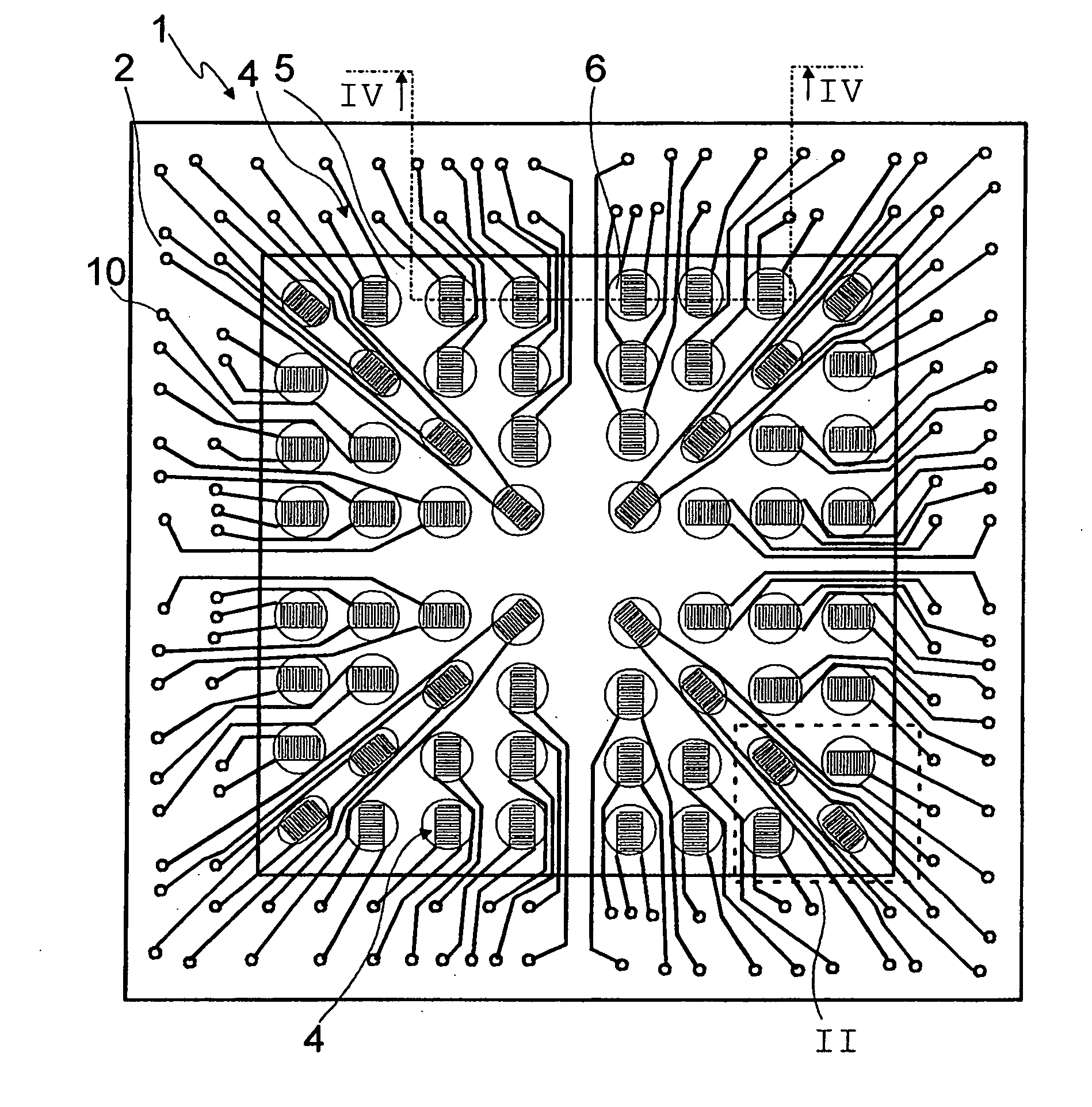
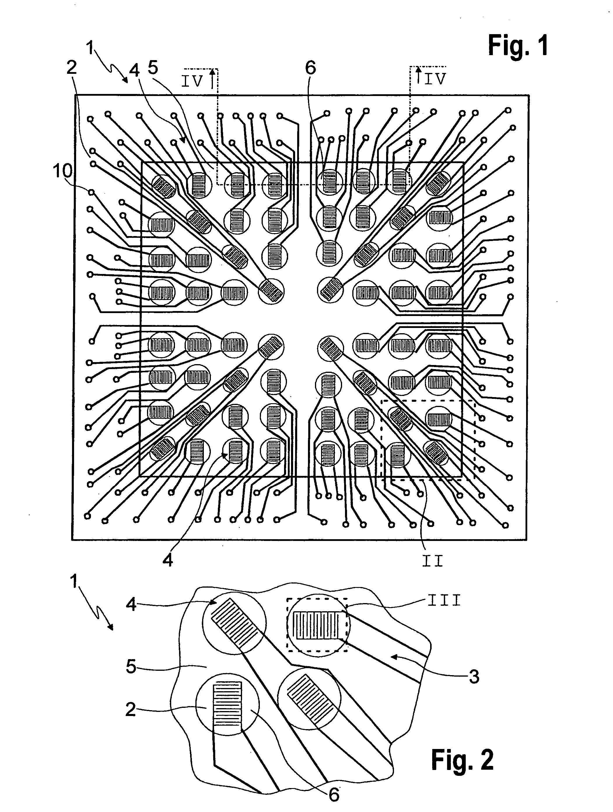
[0015]FIG. 1 shows a top view of a measuring device 1, using which preferably simultaneous pH measurements may be performed during high throughput development where a plurality of different individual syntheses run simultaneously in parallel reactors. Using measuring device 1 having a plurality of potentiometric sensor devices preferably working by the Severinghaus principle, a plurality of reactions running simultaneously or sequentially may thus be continuously tracked in a cost-effective manner in minimum space.

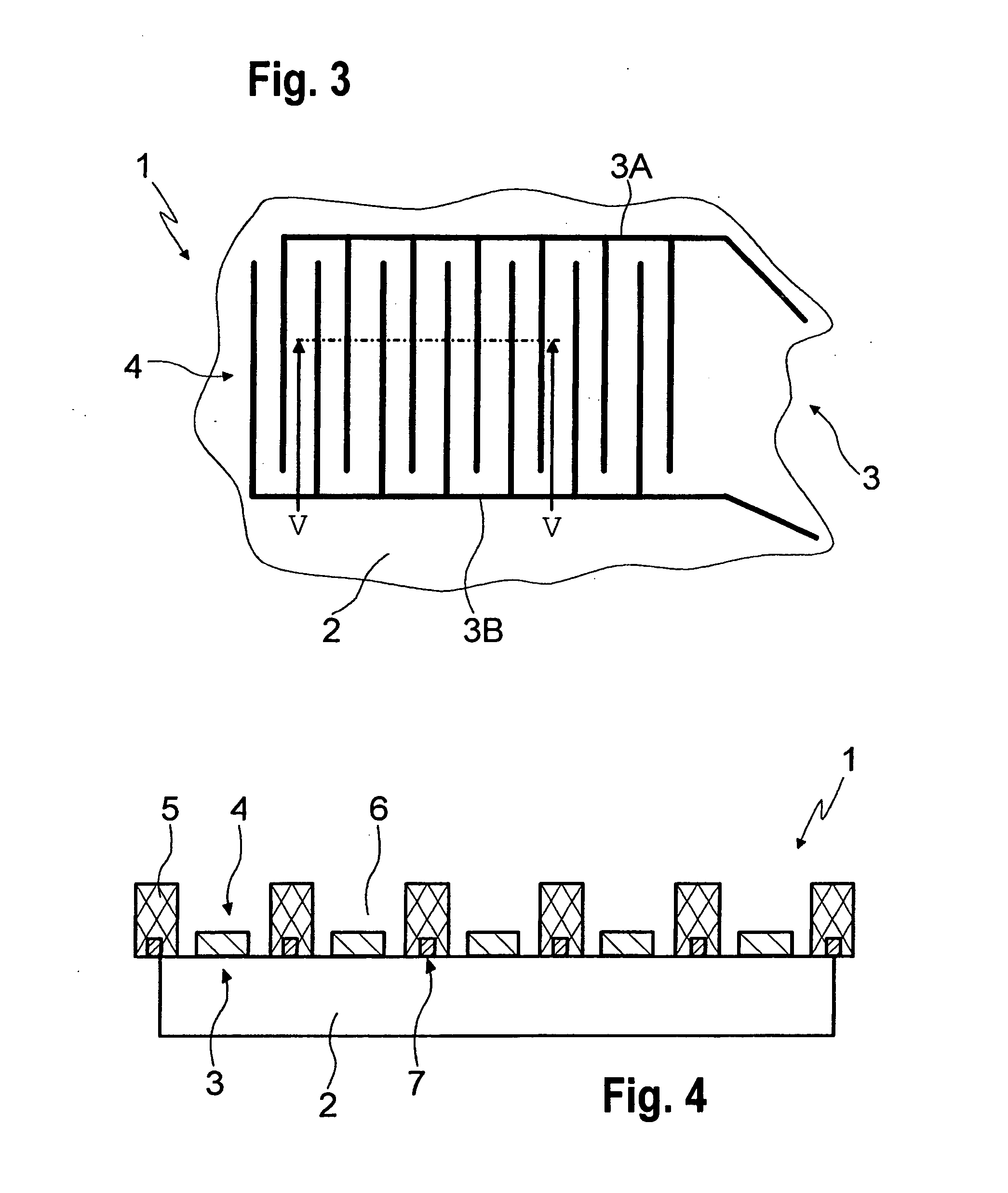
[0016] Measuring device 1 has a substrate 2, on which 64 potentiometric sensor devices are situated, each having a potentiometric electrode pair 3. Substrate 2 is designed here as a ceramic foil made of low-temperature sintering glass-ceramic substrate such as a low-temperature cofiring ceramic (LTCC), which is characterized by a very low electrical conductivity and very good mechanical stability. Alternatively, the substrate may also be manufactured of aluminum oxide, al...


PUM

PropertyMeasurementUnit
areaaaaaaaaaaa
pHaaaaaaaaaa
electric voltageaaaaaaaaaa

Abstract

A measuring device having a plurality of potentiometric electrode pairs situated on a substrate is described. One of the electrodes of each electrode pair represents a reference electrode and the other electrode represents a pH-sensitive working electrode. The electrode pairs form an interdigital structure, and the substrate is covered by a mask in such a way that the individual electrode pairs are separated from one another at least in the area of the interdigital structures of the electrode pairs.

Description

FIELD OF THE INVENTION [0001] The present invention relates to a measuring device having a plurality of potentiometric electrode pairs situated on a substrate, one of the electrodes of each electrode pair representing a reference electrode and the other electrode representing a pH-sensitive working electrode. BACKGROUND INFORMATION [0002] Measuring devices known from industry such as electrochemical sensors or the like are used, for example, for determining a pH value of a liquid medium or even for determining a carbon dioxide component of a medium. Measuring devices designed for such purposes include potentiometric electrode pairs which may be constructed in different ways. [0003] German Patent Application No. 44 24 213, German Published Patent Application No. 195 15 065, and German Published Patent Application No. 298 00 998 describe potentiometric sensors whose operation is based on the long-known principle that an electric voltage, which changes with the change in a chemical spe...

Claims


Application Information

Patent Timeline
Patent Type & Authority Applications(United States)
IPC IPC(8): G01N27/30G01N27/333G01N27/416
CPCG01N27/4162
Inventor BRINZ, THOMASLEWIS, JANE
Owner ROBERT BOSCH GMBH
Learn More