Optical system, in particular illumination system, of a microlithographic projection exposure apparatus

an exposure apparatus and optical system technology, applied in the direction of photomechanical apparatus, printers, instruments, etc., can solve the problems of undesirable effect on relatively difficult control of the polarization state of the projection light passing through, and undesirable affecting the polarization state of the projection light, etc., to achieve the effect of improving the control of the polarization of the projection ligh

Active Publication Date: 2005-07-14
CARL ZEISS SMT GMBH
View PDF7 Cites 23 Cited by
  • Summary
  • Abstract
  • Description
  • Claims
  • Application Information

AI Technical Summary

Benefits of technology

[0010] It is an object of the invention to be able to improve the control over the polarization of p

Problems solved by technology

However, the subsequent optical elements can undesirably affect the polarization state of the projection light.
If a rod homogenizer is being used for mixing the light, for example, then it is relatively difficult to control the polarization state of the pr

Method used


Image

  • Optical system, in particular illumination system, of a microlithographic projection exposure apparatus
  • Optical system, in particular illumination system, of a microlithographic projection exposure apparatus
  • Optical system, in particular illumination system, of a microlithographic projection exposure apparatus

Examples


second embodiment

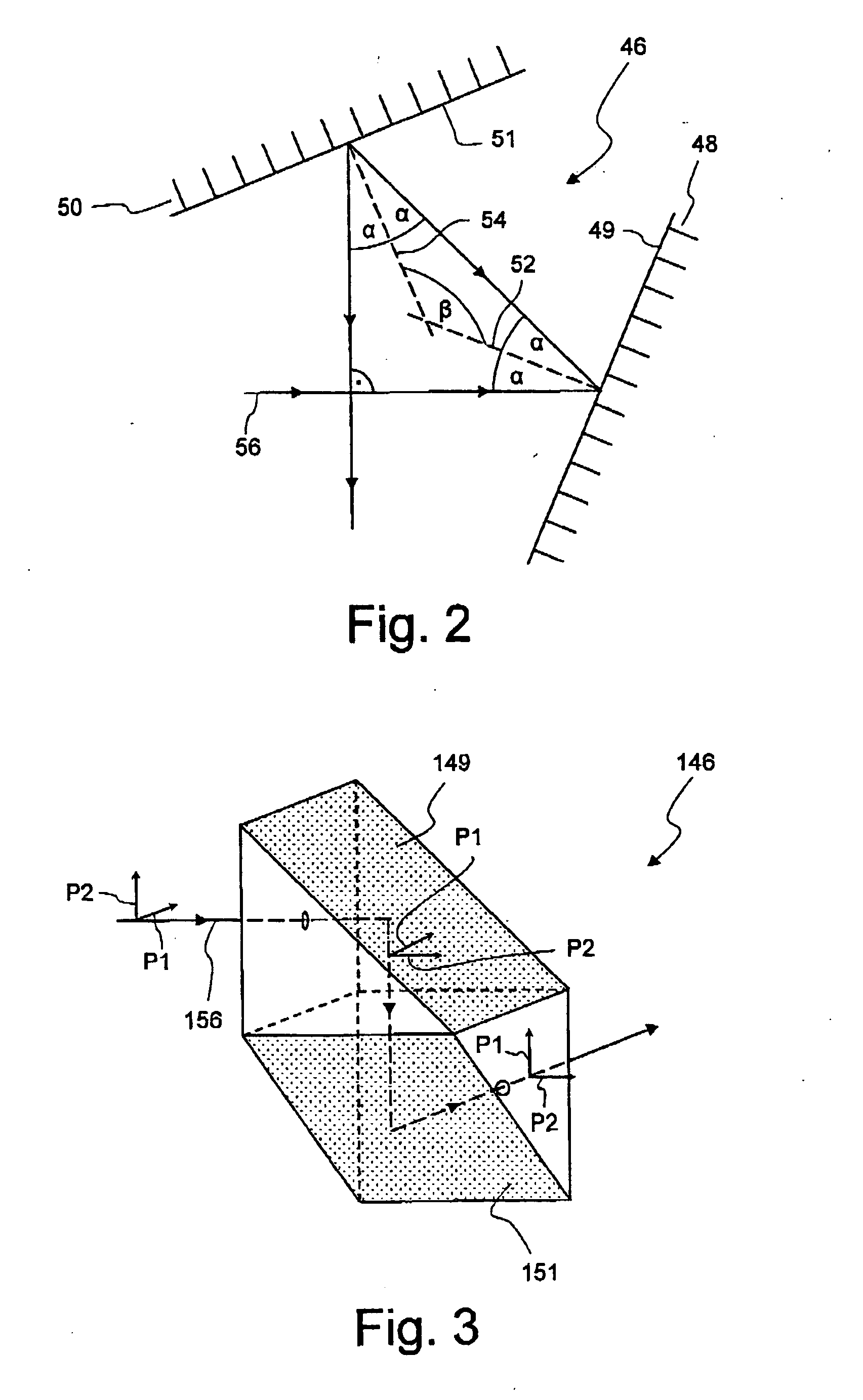
[0046]FIG. 3 represents the second deviating optics in accordance with a second embodiment, in perspective. The second deviating optics are configured here as a Nachet prism 146. For the sake of clarity, the Nachet prism 146 in FIG. 3 is rotated so that an axially parallel ray 156 arriving from the left-hand side does not leave the Nachet prism 146 downwards but into the plane of the paper. By rotating the Nachet prism 146 by 90° about a horizontal axis, the ray 156 can be deviated in the same direction as that represented in FIG. 2.

[0047] The Nachet prism 146 contains a first reflecting surface 149 and a second reflecting surface 151, which are formed by suitable coatings and the normals of which make an angle of 60° between each other. The reflecting surfaces 149, 151 are furthermore mutually arranged so that the axially parallel incident light ray 156 arrives with an angle of incidence of 45° at the first reflecting surface 149, and subsequently arrives at the second reflecting s...

third embodiment

[0050]FIG. 4 shows second deviating optics, denoted overall by 246, in accordance with a third embodiment in a similar representation to FIG. 2. A first plane mirror 248 and a second plane mirror 250 are mutually arranged in the deviating optics 246 so that an incident axially parallel light ray 256 arrives with a relatively large angle of incidence a at a reflecting surface 249 of the first plane mirror 248. The second plane mirror 250 is aligned so that the ray reflected by the first plane mirror 248 arrives with approximately the same angle of incidence a at its reflecting surface 251.

[0051] Between the two plane mirrors 248, 250, a half-wave plate 60 is arranged so that the polarization directions of light passing through are rotated by 90°. In this way, a similar effect is achieved as with the Nachet prism 146. Specifically, the s-component and the p-component of the ray 256 exchange their roles when passing through the half-wave plate 60, so that the polarization component whi...


PUM


Abstract

An optical system, particularly an illumination system, of a microlithographic projection exposure apparatus contains at least one plane reflecting surface for folding the beam path. The at least one reflecting surface is arranged with respect to an optical axis of the optical system such that the intensity ratio between two mutually perpendicular polarization directions is at least substantially preserved for an axially parallel light ray deviated by the at least one reflecting surface. In accordance with a second aspect, the at least one reflecting surface is arranged such that a maximum effect on the polarization of the projection light is achieved, so as to be able to compensate for polarization dependencies which occur in other components of the illumination system.

Description

CROSS-REFERENCE TO RELATED APPLICATIONS [0001] This application claims priority of German Patent Application DE 103 59 849.9, filed Dec. 19, 2003. The full disclosure of this application is incorporated herein by reference. BACKGROUND OF THE INVENTION [0002] 1. Field of the Invention [0003] The invention relates to an optical system for microlithographic projection exposure apparatuses, such as are used for the production of large-scale integrated electrical circuits and other microstructured components. The invention relates in particular to illumination systems having a plurality of reflecting surfaces for folding the beam path. [0004] 2. Description of Related Art [0005] Integrated electrical circuits and other microstructured components are conventionally produced by applying a plurality of structured layers to a suitable substrate which, for example, may be a silicon wafer. In order to structure the layers, they are first covered with a photoresist which is sensitive to a light...

Claims


Application Information

Patent Timeline
IPC IPC(8): G02B27/00G02B27/28G03F7/20
CPCG02B5/04G02B5/3066G03F7/70566G03F7/70191G02B27/286
Inventor GRUNER, TORALFTOTZECK, MICHAELFIOLKA, DAMIANULRICH, WILHELMFUERTER, GERHARD
Owner CARL ZEISS SMT GMBH
Why Eureka
Try Eureka