IP device, management server, and network system

Inactive Publication Date: 2005-07-14
PANASONIC CORP
View PDF2 Cites 116 Cited by
  • Summary
  • Abstract
  • Description
  • Claims
  • Application Information

AI Technical Summary

Benefits of technology

[0014] Therefore, an object of the invention is to provide a device which can be assigned with a port number for port forwarding and can be accessed from a wide area network side by registering address data in a management server on the wide area network. Furthermore, another

Problems solved by technology

However, with the current IP protocol IPv4, the absolute number of global IP addresses is insufficient, so that the shortage of global IP addresses is covered by using the NAT (Network Address Translation) function and the port forwarding function (static IP masquerade).
However, since the port number is automatically selected, a user on the Internet side cannot know which port number is assigned to which of the terminals.
From the inside of the LAN, port numbers to be used by each of the terminals can be confirmed by using a user interface (web page) of a router or a terminal, however, from the Internet side (outside), a user interface of a router cannot be used by reason of security.
However, when images of the plurality of network cameras are browsed from a client terminal, the terminal must access the network cameras one by one, and the access time becomes long and this is troublesome and inconvenient.
Furthermore, when port forwarding setting is dyna

Method used


Image

  • IP device, management server, and network system
  • IP device, management server, and network system
  • IP device, management server, and network system

Examples


Example

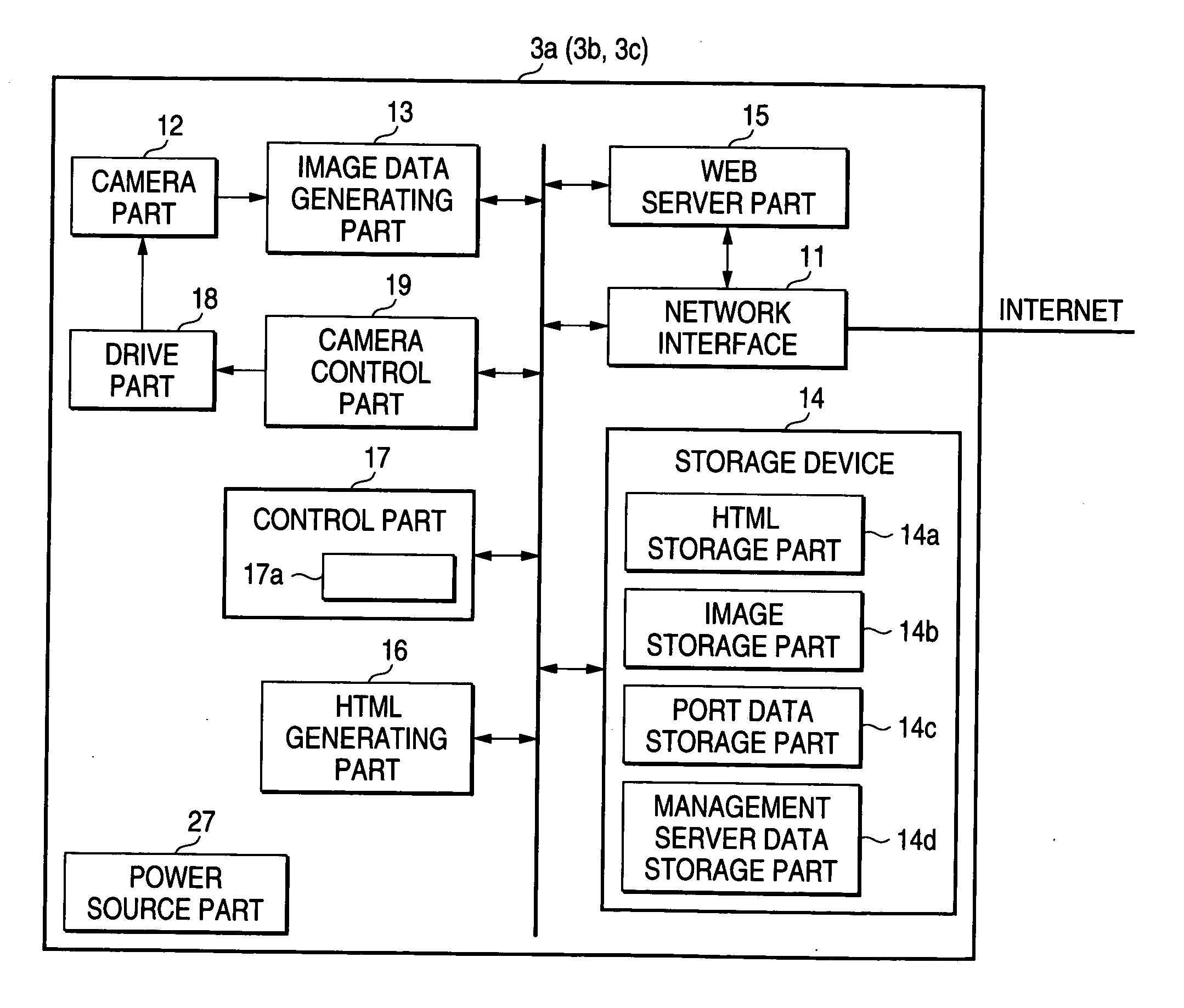
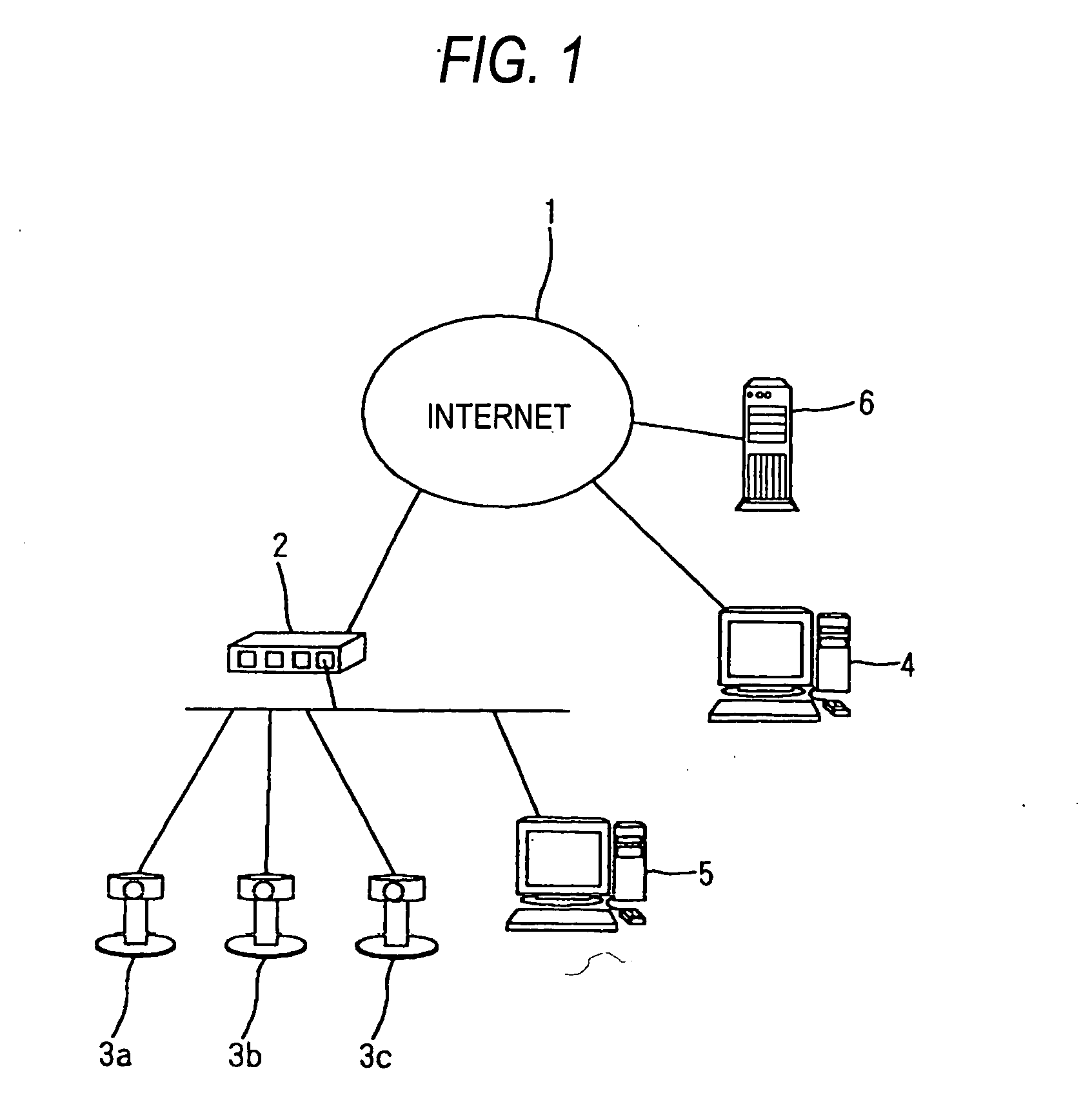
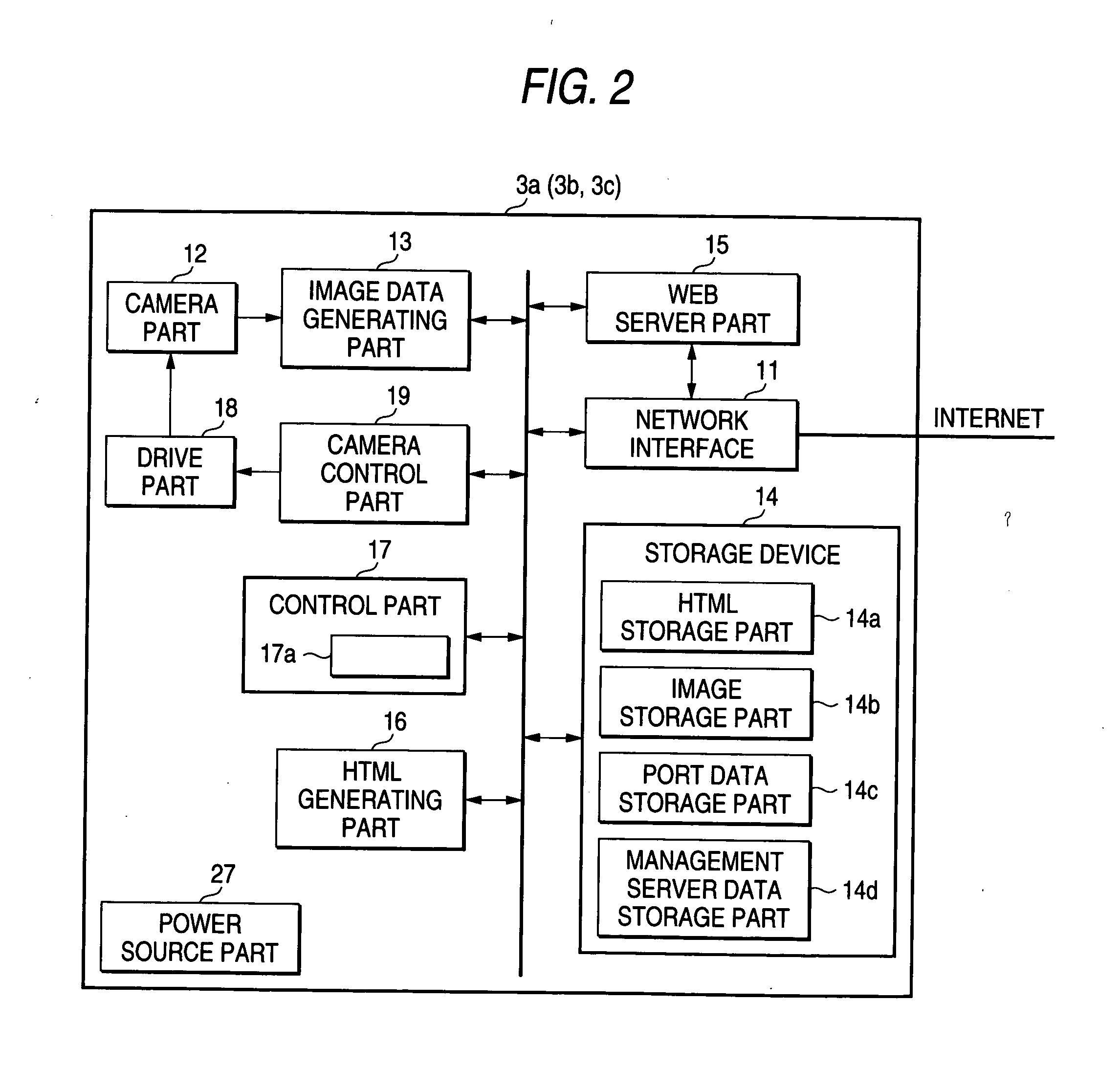
[0039] IP devices under a router and a management server on the Internet in Embodiment 1 of the invention are described. FIG. 1 is a construction diagram of a network system in which access to network cameras under the router is made in Embodiment 1 of the invention, and FIG. 2 is a function block diagram of the network camera in Embodiment 1 of the invention, and FIG. 3 is a construction diagram of a management server in Embodiment 1 of the invention.

[0040] In FIG. 1, the reference numeral 1 denotes the Internet (a wide area network of the invention). The reference numeral 2 denotes a router (a router of the invention) that has an interface connectable to the Internet 1, has a plurality of LAN side ports, and performs routing for subordinate IP devices (for example, network cameras 3a, 3b, and 3c described later), and has a function of dynamic port forwarding of an IP packet according to, in particular, the UPnP standards. The reference numerals 3a, 3b, and 3c denote network camer...

Example

Embodiment 2

[0079] The network cameras, the management server on the Internet, and the router in Embodiment 2 of the invention are described. Even in Embodiment 2, the router 2 has a WAN (Wide Area Network) interface connectable to the Internet 1, and has a plurality of LAN side ports and performs routing for each subordinate IP device, and further has a UPnP function for dynamically setting of port forwarding according to the UPnP standards. The network cameras (IP devices of the invention) 3a, 3b, and 3c are provided with DHCP and UPnP functions for delivering images by protocol TCP / IP. The management server 6 is also provided with a DDNS (Dynamic DNS) function for replying the global IP addresses (hereinafter, referred to as WAN side IP addresses) of the network cameras 3a, 3b, and 3c. When domain names are provided and registered for the network cameras 3a, 3b, and 3c, by accessing with the domain name, connection to each network camera 3a, 3b, or 3c can be made without being c...

Example

Embodiment 3

[0120] Hereinafter, an embodiment which makes it possible to display a list of images from a plurality of cameras on a portal screen is described. FIG. 14 is a construction diagram of a network system containing network cameras in Embodiment 3 of the invention, FIG. 15(a) is a functional block diagram of a network camera in Embodiment 3 of the invention, FIG. 15(b) is an explanatory view of the functional configuration of programs for automatic setting to be installed in the network camera of (a), FIG. 16 is an explanatory view of portal screen display data in Embodiment 3 of the invention, FIG. 17(a) is an explanatory view of a setting screen in Embodiment 3 of the invention, FIG. 17(b) is an explanatory view of a display camera registration screen in Embodiment 3 of the invention, FIG. 18 is an explanatory view of a display camera management table, and FIG. 19 is a sequence chart of automatic setting in Embodiment 3 of the invention.

[0121] In FIG. 14, the reference n...


PUM


Abstract

An IP device (for example, network cameras 3a, 3b, and 3c) connectable to a router (for example, a router 2) makes a request to the router for assignment of a port number when a predetermined operation is performed, and notifies a management server 6 connected to a wide area network of address data containing an assigned port number when the port number is assigned from the router, wherein address data containing the port number can be registered in the management server 6 on the wide area network, so that, even when access is made from the terminal 4 on the wide area network side with a port number that is locally updated, access is made possible by transmitting address data of the IP device to the terminal 4.

Description

BACKGROUND OF THE INVENTION [0001] The present invention relates to an IP device which can register access data in a management server by being connected to a router and assigned with a port number for port forwarding, a management server which registers this access data and provides address data of this IP device to a terminal that accesses via a wide area network, and a network system comprising these. [0002] ADSL and CATV for constant connection to a wide area network such as the Internet have spread on a full scale, and broadband routers have widely spread. However, with the current IP protocol IPv4, the absolute number of global IP addresses is insufficient, so that the shortage of global IP addresses is covered by using the NAT (Network Address Translation) function and the port forwarding function (static IP masquerade). This NAT function converts a local IP address of a LAN-side device into a global IP address of the WAN side of a router when the LAN-side device accesses the...

Claims


Application Information

Patent Timeline
IPC IPC(8): H04L29/06H04L29/08H04L29/12
CPCH04L29/06027H04L61/15H04L29/12047H04L29/12009H04L61/45H04L61/00H04L67/14H04L65/1101
Inventor YOKOMITSU, YASUSHISHUTO, HIDEKIARIMA, YUJITANAKA, MASATAKAOGAWA, HIROFUMI
Owner PANASONIC CORP
Why Eureka
Try Eureka