Method and machine for dynamic ground compaction

a ground compaction and dynamic technology, applied in the direction of hoisting equipment, construction, foundation engineering, etc., can solve the problems of low efficiency, limited impact energy, and the mobile parts consisting of the connection device and possibly the reeving system are kicked upward with a considerable amount of energy, so as to avoid damage to the structure and reduce the time necessary

Active Publication Date: 2005-07-14
FREYSSINET INT STUP
View PDF6 Cites 16 Cited by
  • Summary
  • Abstract
  • Description
  • Claims
  • Application Information

AI Technical Summary

Benefits of technology

[0019] The hoisting is carried out by one or several winches of the “free falling” type (as in the prior methods with follower cable), with the possible use of pulley blocks to multiple the winch effort. The compaction load is hanged to the lower block or directly to the winch cables via releasable connection means, for example of the hook or clamp type. The connection means are released once they have reached a certain downward velocity, so that the connection part which remains attached to the cable is not thrown upwardly. This avoids damages to the structure, without requiring external mooring systems. In addition, the downward velocity of the connection means and the cable when the load is released reduces the time necessary to bring the connection means back into position on the load, after it has landed on the ground.

Problems solved by technology

This low efficiency is due to frictional losses and to the inertia of the cables and winches.
The impact energy is basically limited by the stability of the hoisting machine when loaded.
However, the method also has a number of drawbacks.
The mobile parts consisting of the connection device and possibly of the reeving system are kicked upwardly with a considerable energy.
Such reaction can cause various troubles, such as derailment of the cables, impacts on the crane structure, etc.
In addition, the lowering of the connection device for reconnection to the load on the ground takes a significant amount of time, since it depends on the speed capacity of the unloaded winches, which is usually low.
Therefore, this second method is relatively time-consuming.

Method used


Image

  • Method and machine for dynamic ground compaction
  • Method and machine for dynamic ground compaction
  • Method and machine for dynamic ground compaction

Examples


Embodiment Construction

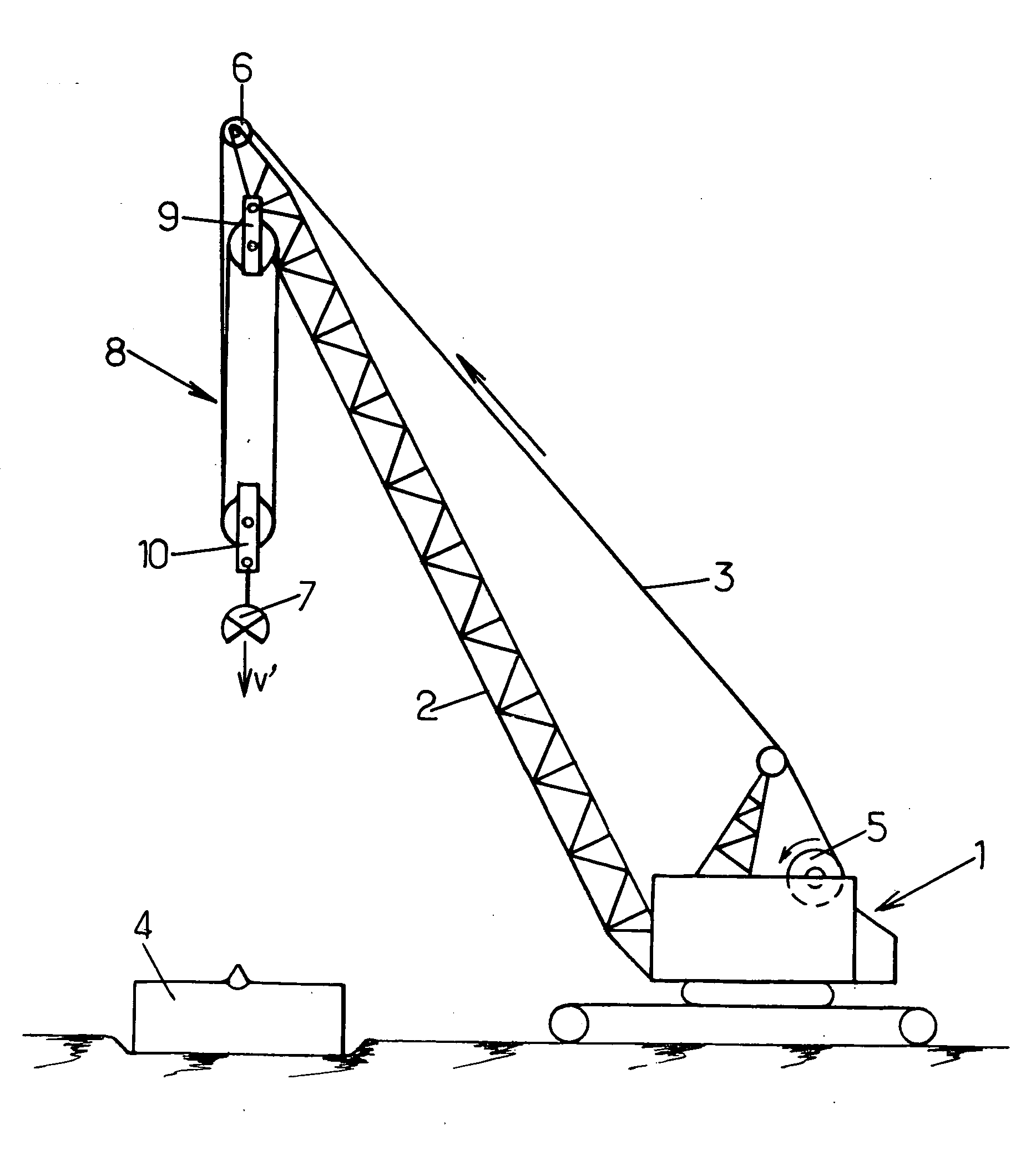
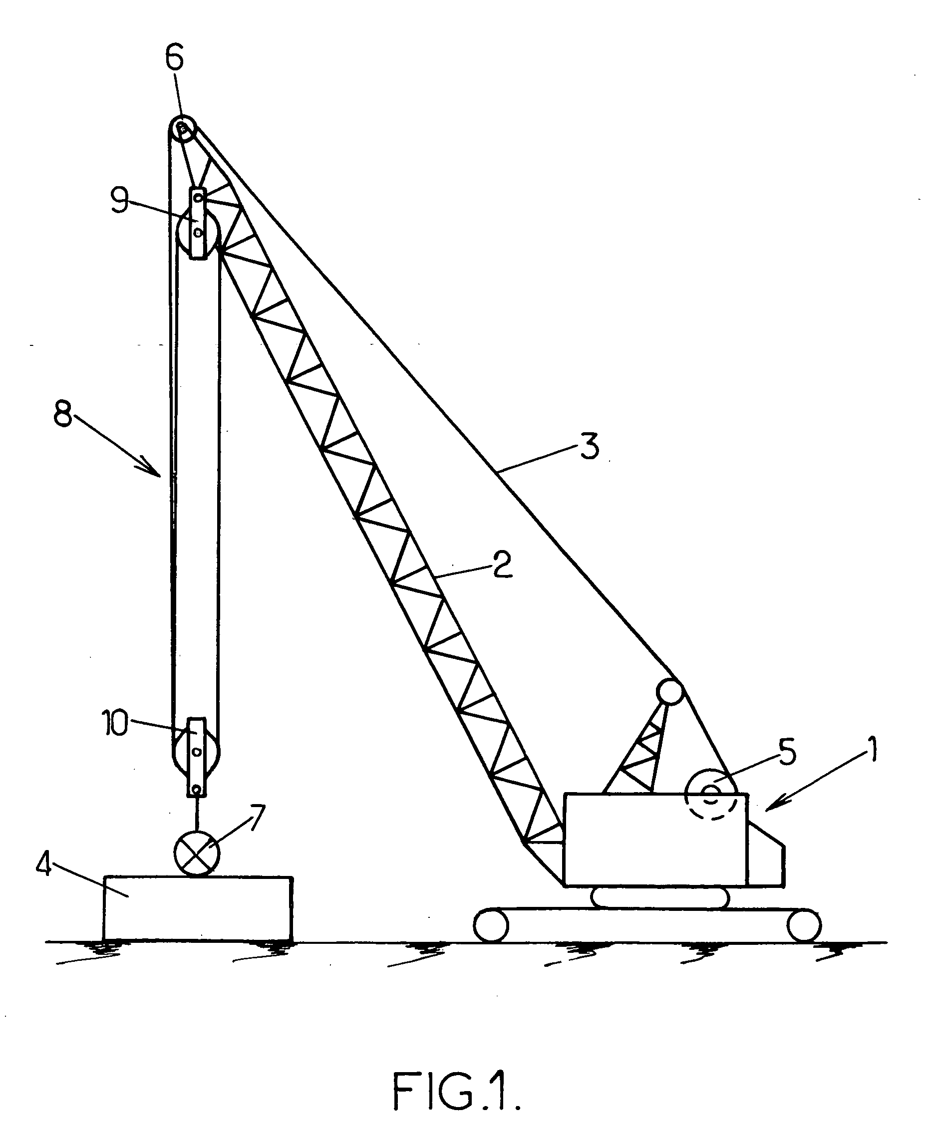
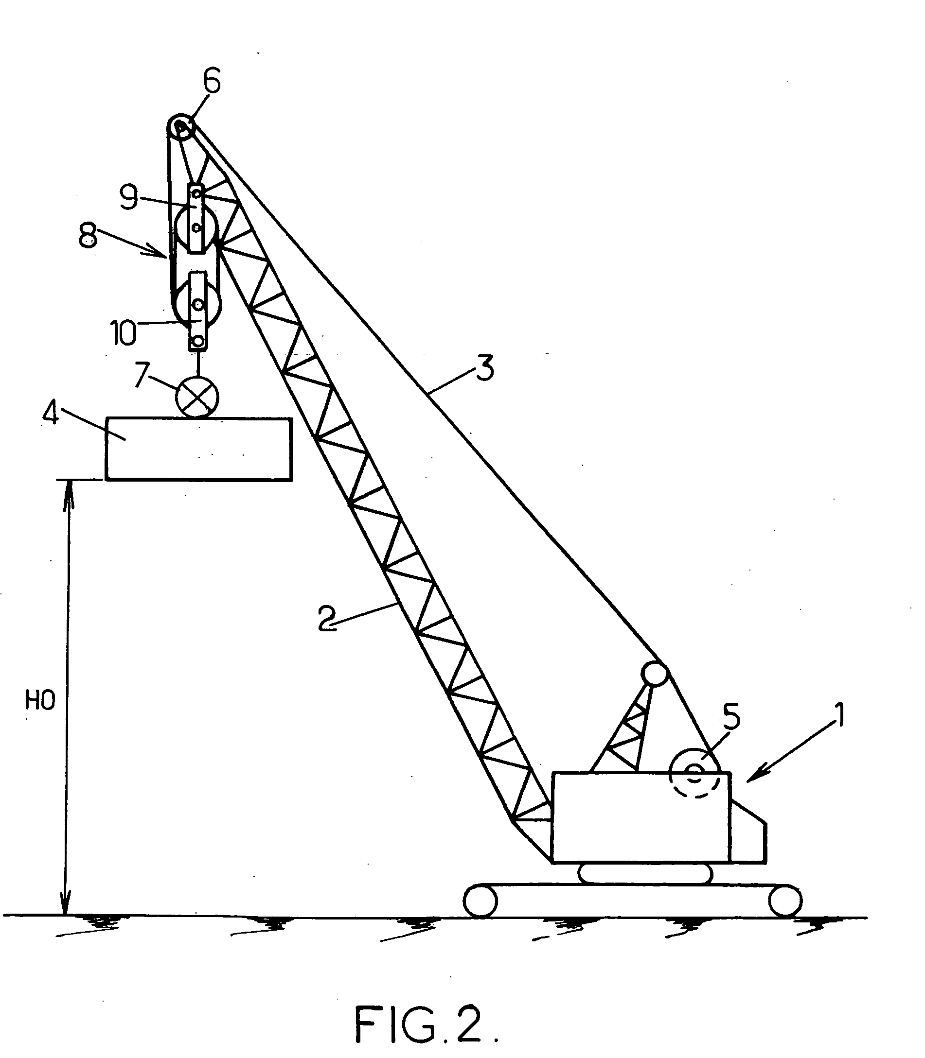
[0023] The ground compaction machine shown in FIGS. 1-4 has a vehicle structure 1 supporting a crane boom 2. One or more cables 3 are used to hoist a heavy load 4 (>10 tons) from the ground level to a predetermined dropping level H0 (>10 m). Each hoisting cable 3 is wound on the drum of a winch 5 mounted on the structure 1, and deviated by a pulley 6 on top of the crane boom 2.

[0024] A releasable connection device 7, schematically shown in FIGS. 1-4, is interposed between the hoisting cable(s) 3 and the compaction load 4.

[0025] In the embodiment illustrated by FIGS. 1-4, the machine further includes a reeving system 8 which receives the hoisting cable 3 between the deviation pulley 6 and the releasable connection device 7. Such system 8 may include an upper pulley block 9 mounted near the top of the crane boom 2 and a lower pulley block 10 whose frame is connected to the connection device 7. The cable 3 is received by the pulleys of blocks 9, 10 in order to multiple the hoisting e...


PUM


Abstract

At least one cable is attached to a load lying on the ground via releasable connection means. A traction force is applied to the cable to hoist the load up to a prescribed height. That traction force is then eliminated or reduced to initiate a downward movement of the load followed by the cable. The connection means are then released while the load is moving downwardly.

Description

BACKGROUND OF THE INVENTION [0001] The present invention relates to dynamic ground compaction techniques. These techniques are used to improve the structural characteristics of the ground, in particular prior to building construction works. [0002] A dynamic compaction treatment densifies the ground down to great depths by means of very high energy waves. It involves heavy loads, typically from 10 to 100 tons, falling from a height of typically 10 to 40 meters. The layout of the impact points on the ground and the other parameters of the treatment (energies, phasing, rest periods) depend on the characteristics of the soil to be treated and possibly on measurement results obtained in a trial zone. These parameters are determined beforehand based on the desired ground characteristics. [0003] Such ground treatment is frequently used for the foundation of buildings, or to stabilized large areas of embankment work or loose soil. [0004] Two general types of dynamic ground compaction method...

Claims


Application Information

Patent Timeline
Patent Type & Authority Applications(United States)
IPC IPC(8): E02D3/00E02D3/02
CPCE02D3/02E02D3/068
Inventor MORIZOT, JEAN-CLAUDE
Owner FREYSSINET INT STUP
Why Eureka
Try Eureka