Imaging system for video endoscope

a technology of endoscope and imaging system, which is applied in the field of medical devices, can solve the problems of affecting the performance of the device, affecting the operation, and affecting the operation, and achieves the effect of improving the device performance and reducing the coefficient of friction of the endoscop

Inactive Publication Date: 2005-07-14
BOSTON SCI SCIMED INC
View PDF11 Cites 245 Cited by
  • Summary
  • Abstract
  • Description
  • Claims
  • Application Information

AI Technical Summary

Benefits of technology

[0007] To address these and other problems in the prior art, the present invention is a video endoscope system. In one aspect, the system includes a control cabinet, a number of manual or electronic actuators that control the orientation of an endoscope and an imaging system to produce images collected by an image sensor at the distal end of the endoscope. The endoscope is connectable with the control cabinet and used to examine and / or treat a patient. After the examination procedure, the endoscope is disconnected from the control cabinet and may be disposed saving the cost and labor of cleaning and resterilization inherent in traditional reusable endoscopes.
[0008] The endoscope of the present invention includes a flexible elongate tube or shaft and an illumination source that directs light onto an examination site. An image sensor and objective lens assembly at or adjacent the distal end of the endoscope captures reflected light to produce an image of the illuminated scene. Images produced by the sensor are transmitted to a display device to be viewed by an operator. In one embodiment, an imaging assembly at the distal end of the endoscope includes an inexpensive mass-produceable assembly of components that house one or more light emitting diodes (LEDs), an image sensor such as a CMOS solid state image sensor and low cost (e.g., plastic) lens assembly. The LEDs may be thermally coupled to a heat exchanger, and air or liquid cooled in order to remove any excess heat generated by the LEDs.
[0009] The endoscope of the present invention also includes a steering mechanism such as a number of tensile control cables, which allow the distal end of the endoscope to be deflected in a desired direction. In one embodiment of the invention, the proximal end of the tensile control cables is connected to a mechanical control mechanism (e.g., knobs)—mounted in a proximal control handle. In another embodiment, the cables communicate with actuators within the control cabinet. In the latter, a directional controller generates electrical control signals which are sent via a processor within the control cabinet, which generates control signals to drive the actuators in order to orient the distal end of the endoscope in the direction desired by the operator. In another embodiment of the invention, the distal end of the endoscope is automatically steered, based on analysis of images from the image sensor. A joystick or other directional controller may include tactile, haptic or other sensory feedback to reflect the force against a tissue wall or to alert the operator that the endoscope may be looped. The distal tip housing provides a high degree of integration of parts—for example, clear windows for the LEDs are insert-molded into the distal tip housing to eliminate any secondary window sealing operations and to ensure a hermetic seal.
[0010] In one embodiment of the invention, the endoscope includes an articulation joint that is comprised of a number of low cost (e.g., machine formed, stamped or molded parts), easily mass produced components that allow the distal end of the endoscope to be bent in a desired direction by the control cables. In one embodiment of the invention, the articulation joint exerts a restoring force such that upon release of a tensioning force, the distal end of the endoscope will straighten.
[0011] In another embodiment of the invention, the endoscope has a variation in stiffness along its length that allows the distal end to be relatively flexible while the more proximal regions of the endoscope have increased column strength and torque fidelity so that an operator can navigate the endoscope with greater ease and accuracy and precision through tortuous, compliant anatomy with fewer false advances (“loops”). A preset variation in mechanical properties (e.g., column strength, bending modulus or strength, torsion) along the length can be provided, for example, by varying the durometer rating or types or dimensions of materials that comprise a shaft of the endoscope. Operator-controlled variable stiffness can be provided by control cables that can be tightened, loosened or torqued to adjust the stiffness of the shaft. In yet another embodiment, the spacing between the components that comprise the articulation joint is selected to provide a preset variation in stiffness along the length of the articulation joint.
[0013] In another embodiment of the invention, the endoscope surface includes a material such as a hydrophilic coating, to reduce the coefficient of friction of the endoscope. Other coatings may be used to, for example, improve the device performance, provide an indication of prior use or contamination or deliver therapeutic agents.

Problems solved by technology

By manipulating the control knobs, the operator is able to steer the endoscope during insertion and direct it to a region of interest, in spite of the limitations of such traditional control systems, which may be bulky, somewhat non-intuitive, and friction-limited.
Common operator complaints about traditional endoscopes include their limited flexibility, limited column strength, and limited operator control of stiffness along the endoscope length.
For example, conventional, flexible endoscopes are expensive medical devices costing in the range of $25,000, and much more with the associated operator console.
The endoscope is expensive because it includes expensive piece parts and requires laborious hand assembly.
These material structures decrease the flexibility of the endoscope and can compromise patient comfort.
Furthermore, conventional endoscopes are complex and fragile instruments that frequently need expensive repair as a result of damage during use or during a disinfection procedure.

Method used


Image

  • Imaging system for video endoscope
  • Imaging system for video endoscope
  • Imaging system for video endoscope

Examples


Embodiment Construction

[0061] As indicated above, the present invention is a video endoscope system that allows an operator to access, and view internal body anatomy of a patient as well as to insert surgical instruments into the patient's body. In addition, the endoscope may include integrated diagnostic and therapeutic capabilities to allow the operator to treat the patient in a single procedure. An endoscope of the present invention can be sufficiently inexpensive to manufacture such that the endoscope can be considered a single use, disposable item.

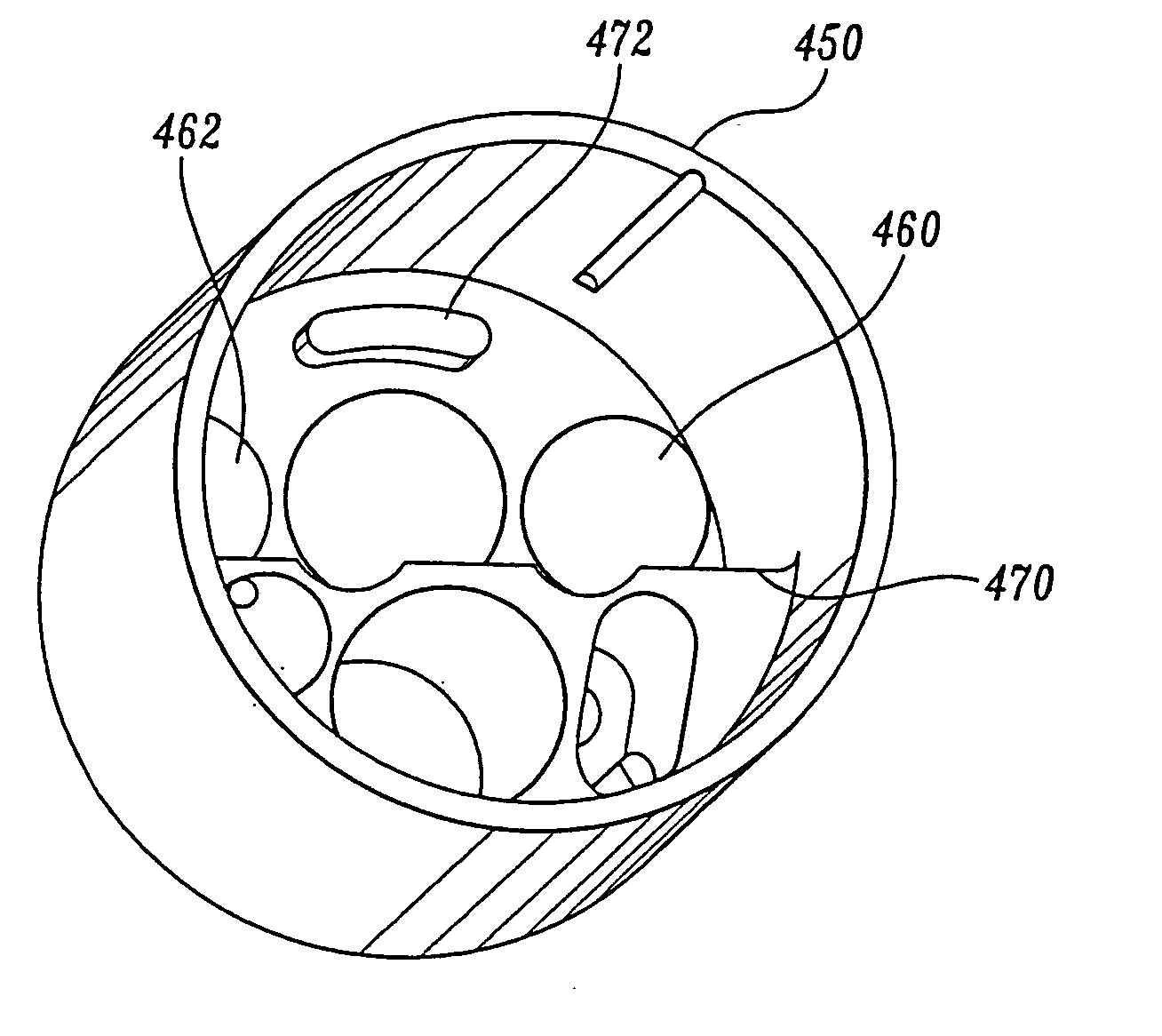
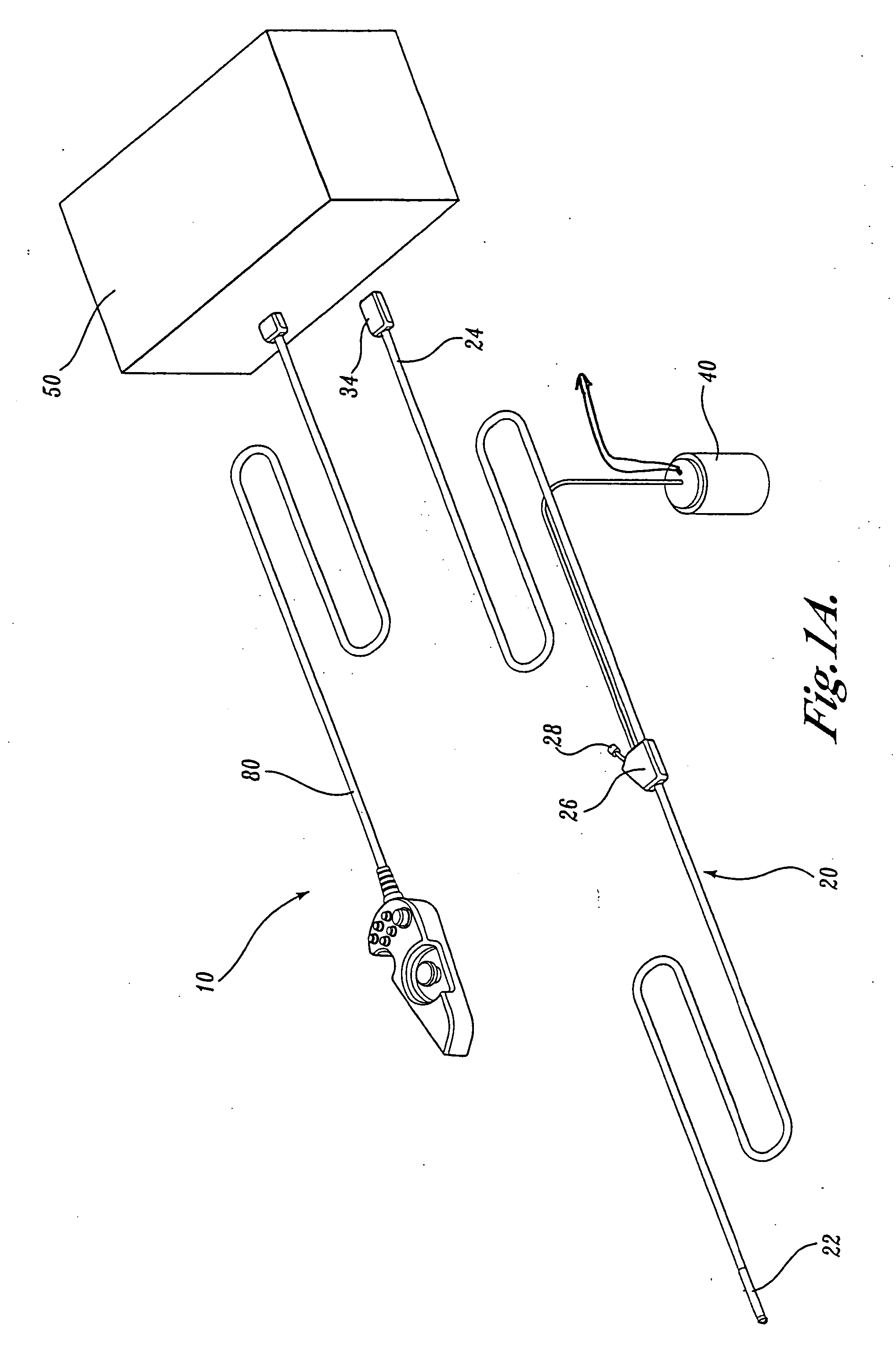
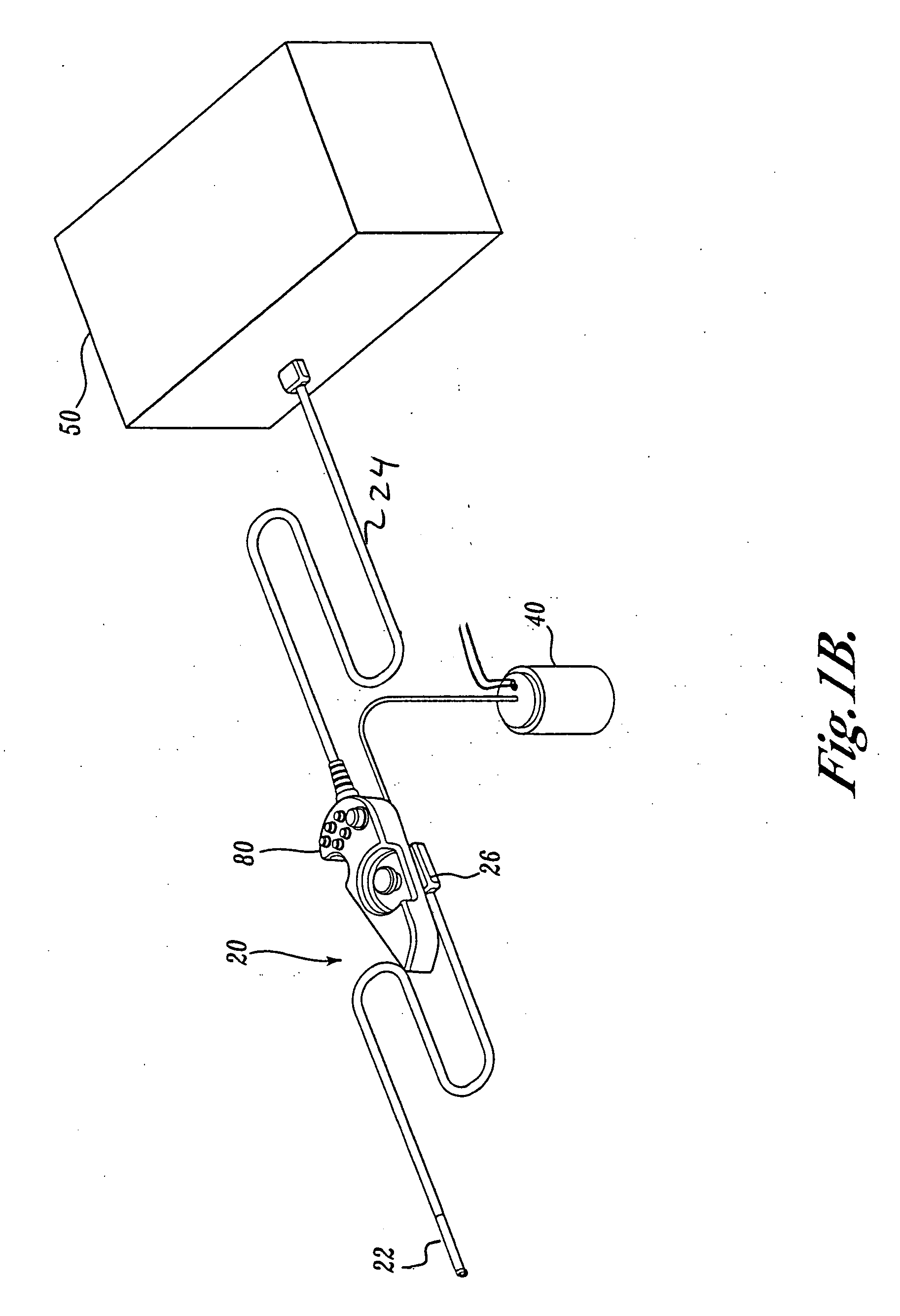
[0062] As shown in FIG. 1A, a video endoscope system 10 according to one embodiment of the present invention includes an endoscope 20, a control cabinet 50 and a handheld controller 80. The endoscope 20 has a distal tip 22 that is advanced into a patient's body cavity and a proximal end 24 that is connected to the control cabinet 50. As will be explained in further detail below, the control cabinet 50 includes a number of actuators that control a steering ...


PUM


Abstract

A video endoscope system includes a reusable control cabinet and an endoscope that is connectable thereto. The endoscope may be used with a single patient and then disposed. The endoscope includes an illumination mechanism, an image sensor, and an elongate shaft having one or more lumens located therein. An articulation joint at the distal end of the endoscope allows the distal end to be oriented by the actuators in the control cabinet or actuators in a control handle of the endoscope. Fluidics, electrical, navigation, image, display and data entry controls are integrated into the system along with other accessories.

Description

CROSS-REFERENCE TO RELATED APPLICATION [0001] The present application is a continuation-in-part of U.S. patent application Ser. No. 10 / 811,781, filed March 29, 2004, which is a continuation-in-part of U.S. patent application Ser. No. 10 / 406,149, filed Apr. 1, 2003, the benefits of which are claimed under 35 U.S.C. § 120 and are herein incorporated by reference.FIELD OF THE INVENTION [0002] The present invention relates to medical devices in general and therapeutic and diagnostic endoscopes in particular. BACKGROUND OF THE INVENTION [0003] It has become well established that there are major public health benefits from regular endoscopic examinations as an aid to the early detection and treatment of disease of internal structures such as the alimentary and excretory canals and airways, e.g., the colon, esophagus, stomach, urethra, bladder, ureter, kidney, lungs, bronchi, uterus and other organ systems. A conventional imaging endoscope used for such procedures comprises a flexible tube...

Claims


Application Information

Patent Timeline
Patent Type & Authority Applications(United States)
IPC IPC(8): A61B1/005A61B1/015A61B1/05A61B1/31
CPCA61B1/00059A61B1/0016A61B1/0008A61B1/00147A61B1/0051A61B1/0052A61B1/0055A61B1/015A61B1/05A61B1/0653A61B1/0676A61B1/0684A61B1/31A61B1/128A61B1/00071
Inventor BANIK, MICHAEL S.COUVILLON, LUCIEN ALFRED JR.BOULAIS, DENNIS R.FANTONE, STEPHEN D.ORBAND, DANIEL G.SABER, MICHAEL P.BRAUNSTEIN, DANIEL J.
Owner BOSTON SCI SCIMED INC
Why Eureka
Try Eureka