Apparatus and method for measuring a fluid velocity profile using acoustic doppler effect

a technology of fluid velocity and doppler effect, applied in the field of apparatus and method for measuring fluid velocity profile using acoustic doppler effect, can solve the problem of inaccurate measurement of flow rate profil

Inactive Publication Date: 2005-07-14
FUJI ELECTRIC SYST CO LTD
View PDF8 Cites 12 Cited by
  • Summary
  • Abstract
  • Description
  • Claims
  • Application Information

AI Technical Summary

Benefits of technology

[0035] Another aspect of the present invention is the method of measuring a flow rate profile of fluid, traveling in the tubular body, based on the frequency of ultrasound changed by the Doppler effect when ultrasound is reflected by the reflectors existing in the fluid. The method can comprise the steps of mounting externally on the tubular body, the w...

Problems solved by technology

As described above, the Doppler ultrasound flow meter for calculating the flow rate by measuring the flow rate profile in the piping has a problem in that an acoustic wave transmitted from the ultrasound transducer generates a longitudinal wave and a shear...

Method used


Image

  • Apparatus and method for measuring a fluid velocity profile using acoustic doppler effect
  • Apparatus and method for measuring a fluid velocity profile using acoustic doppler effect
  • Apparatus and method for measuring a fluid velocity profile using acoustic doppler effect

Examples


first embodiment

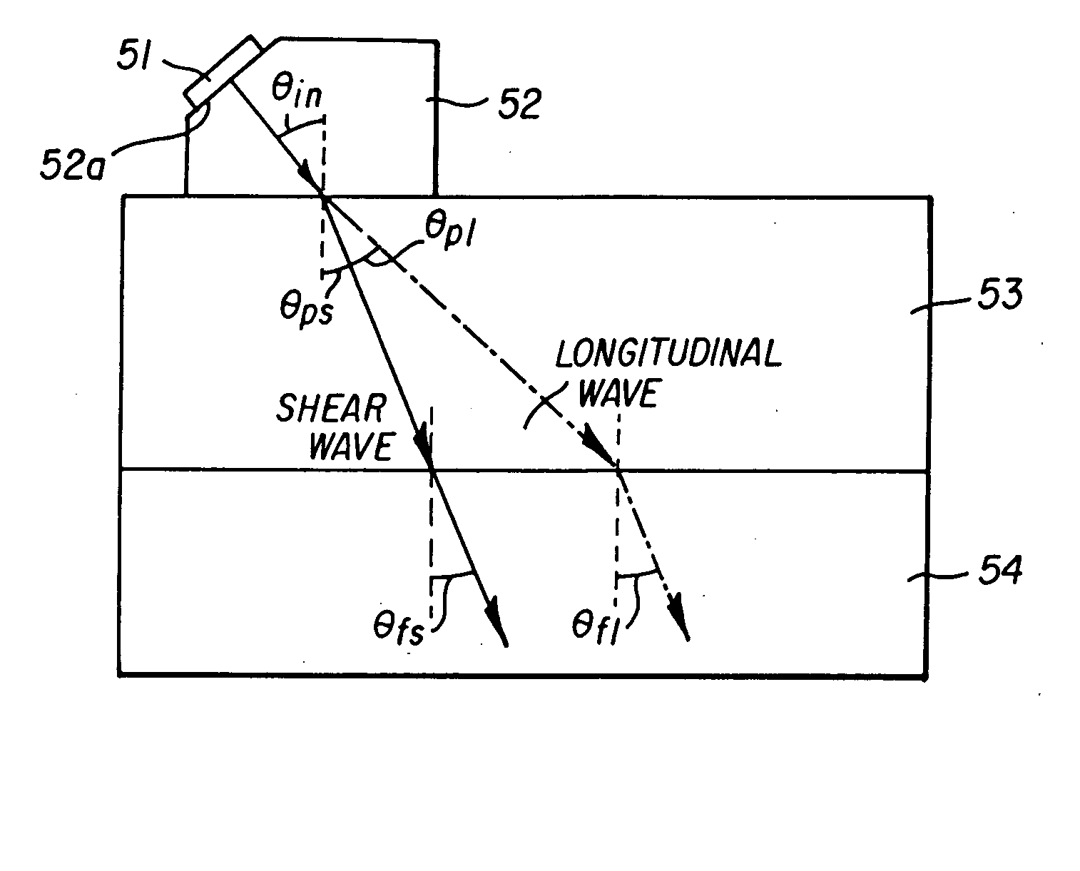
[0050]FIG. 1 shows the main part of the Although the structure of FIG. 1 include substantially the same components as included in FIG. 9, FIG. 12, FIG. 13, etc., different reference numerals are used, for clarity. Reference numeral 51 denotes an ultrasound transducer, which generates an acoustic wave. This ultrasound oscillator or transducer 51 can be made of a piezoelectric material, such as PZT (e.g., zircon, lead titanate) and operates both as an ultrasound transmitter / receiver. Reference numeral 52 denotes a wedge made of a resin material in which an acoustic wave can propagate (e.g., acrylic, epoxy resin, polyvinyl chloride, polyphenylene sulfide). The wedge 52 has an inclined plane 52a at the upper end thereof, and the ultrasound transducer 51 can be fixed to the inclined plane 52a with an epoxy adhesive agent or the like. The inclined plane 52a is inclined such that the oblique angle of the ultrasound transducer 51 to the direction perpendicular to the longitudinal direction...

second embodiment

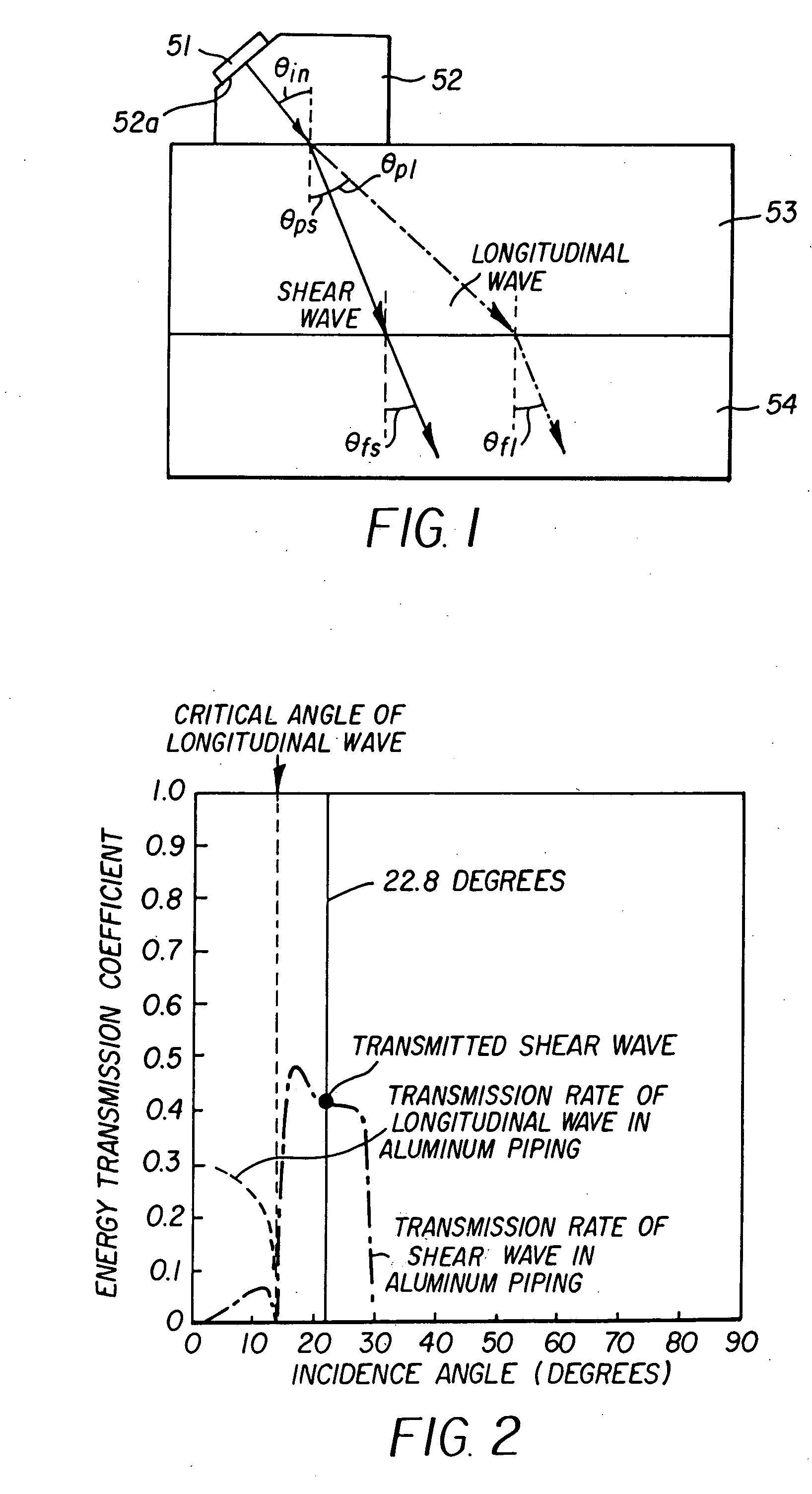
[0060] In the present invention, only the longitudinal wave element of the ultrasound echo propagating in the piping 53 after being reflected by the reflector in the fluid 54 is eliminated. It is assumed that, when the fluid 54 is water, for example, the critical angle of the longitudinal wave in the ultrasound echo transmitted into the aluminum piping 53 after being reflected by the reflector in water is 13.5 degrees while the critical angle of the shear wave is 29.6 degrees when the acoustic wave in water is 1500 m / s.

[0061] Thus, when the acoustic wave from the piping 53 into water has an incidence angle that is equal to or higher than 13.5 degrees and that is equal to or lower than 29.6 degrees, then only the shear wave element is transmitted into the piping 53 and the longitudinal wave element is eliminated when the ultrasound echo is transmitted from water into the piping 53, thus reducing the acoustic noise caused by the longitudinal wave. As a result, the ultrasound transduce...


PUM


Abstract

A clamp-on type acoustic Doppler current profiler eliminates, among ultrasound echoes caused by two measurement lines of a longitudinal wave and a shear wave propagating in a piping, the ultrasound echo based on the longitudinal wave, thereby providing the measurement of a flow rate profile and/or a flow rate with a higher accuracy. The profiler includes a wedge mounted to the piping. The wedge includes an inclined surface at which an ultrasonic transducer can be mounted. The inclination is such that the ultrasound transducer receives only the ultrasound echo from the reflection of a shear wave component off the reflectors in the fluid.

Description

BACKGROUND [0001] A clamp-on type ultrasound flow meter typically uses an ultrasound transducer attached to a part of an outer periphery of a tubular body, such as a piping, to measure, from the exterior of the tubular body, the flow rate of fluid moving in the tubular body. Clamp-on type ultrasound flow meters are mainly classified into ones that utilize the difference in propagation time and ones that utilize the Doppler effect. [0002] The former ones based on the difference in propagation time reciprocate ultrasound, applied slantedly across the tubular body to the fluid moving in the tubular body. The difference between the time in which the ultrasound propagates along the outward route and the time in which the ultrasound propagates along the return route is used to measure the fluid flow rate. [0003] On the other hand, the latter ones, based on the Doppler effect, relies on reflectors, namely suspended particles and / or air bubbles included in the fluid, which are assumed to mo...

Claims


Application Information

Patent Timeline
IPC IPC(8): G01F1/66
CPCA61B8/485G01F1/662
Inventor HIRAYAMA, NORITOMOYAMAMOTO, TOSHIHIROYAO, HIRONOBU
Owner FUJI ELECTRIC SYST CO LTD
Why Eureka
Try Eureka