Sensor arrangement

Inactive Publication Date: 2005-07-21
ROBERT BOSCH GMBH
View PDF2 Cites 46 Cited by
  • Summary
  • Abstract
  • Description
  • Claims
  • Application Information

AI Technical Summary

Benefits of technology

[0006] An example embodiment of a sensor system according to the present invention may have the advantage that the necessary alignment of the sensor in the receiving element is able to be ensured for an existing sensor design having hollow screw fixing of the sensor in the receiving element by simply minimally changing the manufacturing method and without changing the

Problems solved by technology

As a result, condensation water included in the exhaust gas is not able to reach the protruding end of the measuring el

Method used


Image

  • Sensor arrangement
  • Sensor arrangement
  • Sensor arrangement

Examples


Embodiment Construction

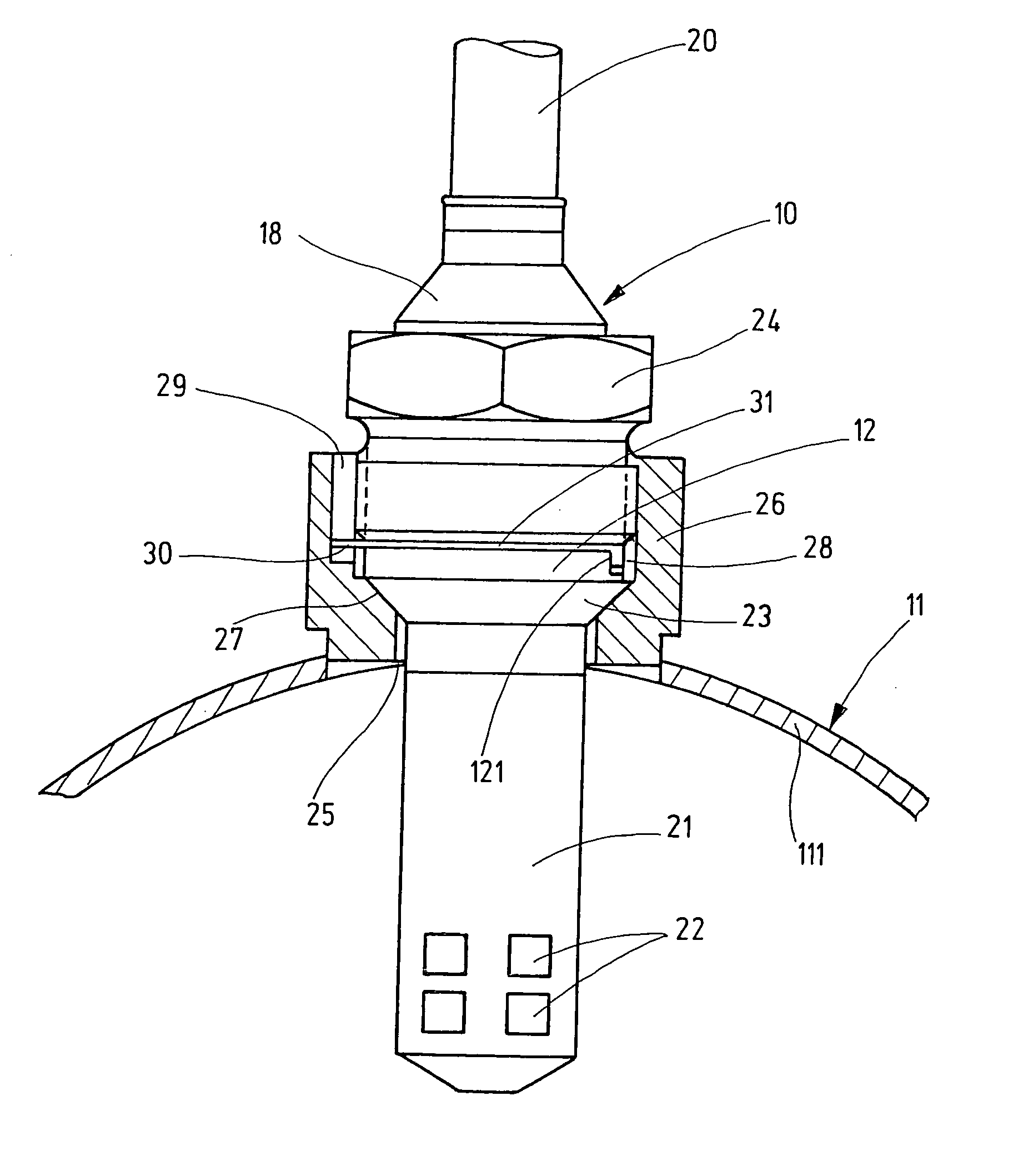
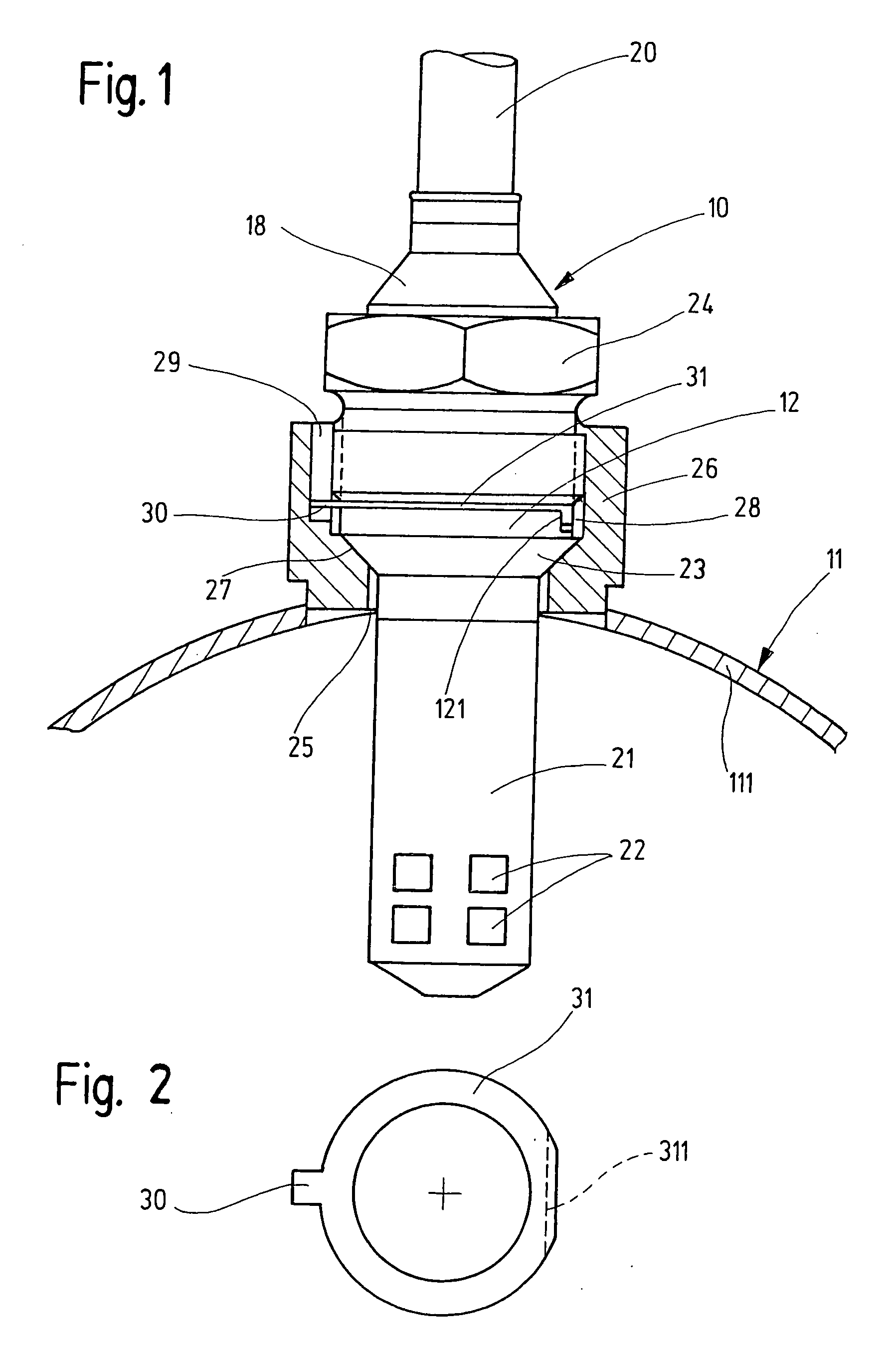
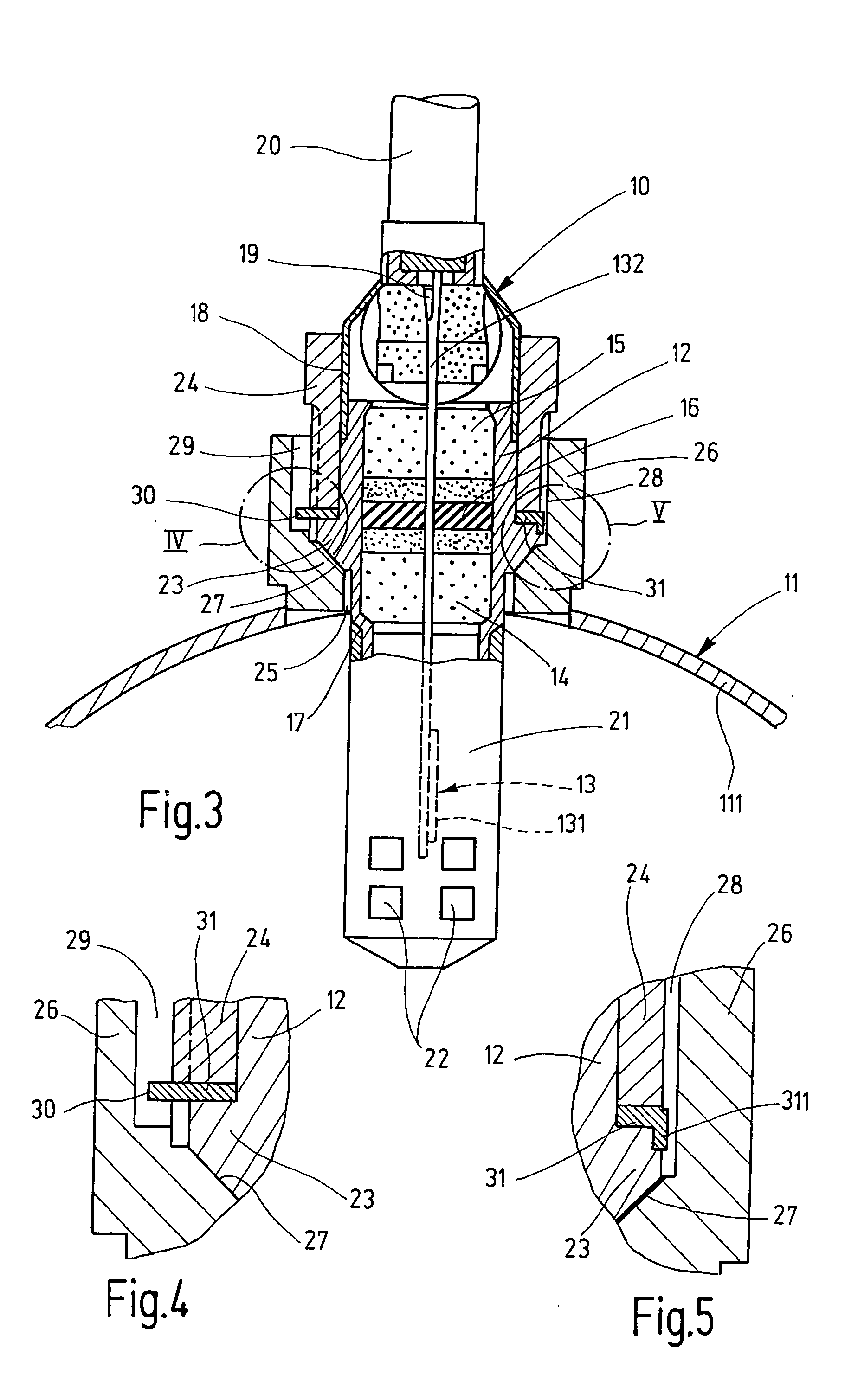
[0015] The sensor system shown in FIGS. 1 and 3 has a sensor 10 for measuring a gas parameter of a test gas, shown as a side view in FIG. 1 and as a longitudinal section in FIG. 3, and a test-gas line 11, through which a test gas flows, shown sectionally as a cross section in FIGS. 1 and 3. In the example in FIGS. 1 and 3, sensor 10 is a lambda probe for measuring oxygen concentration as the gas parameter in the exhaust gas of an internal combustion engine, and test-gas line 11 is an exhaust-gas pipe outgoing from one or more combustion cylinders of the internal combustion engine.

[0016] Sensor 10 has a sensor or a measuring element 13 (FIG. 3), which is accommodated in a housing 12 and protrudes therefrom at a section 131 on the test gas side and a section 132 on the connection side. In this context, measuring element 13 is surrounded by an electrically insulating ceramic insert 14 on the test gas side, an electrically insulating ceramic insert 15 on the connection side, and an int...


PUM


Abstract

A sensor system having a sensor for measuring a gas parameter of a test gas via a measuring element which is accommodated in a housing and projects therefrom at least on the test gas side at a protruding section, and a test-gas line, through which the test gas flows, having a sensor insertion opening and a receiving element for the housing surrounding the insertion opening and attached to the test-gas line. For the purpose of assembly-independent, reproducible alignment of the measuring element with respect to the test-gas flow during assembly of the sensor system, the receiving element bears an internal thread, the piercing point of which is oriented with respect to the test-gas flow, and the housing bears an external thread, which is able to be screwed into the internal thread and the piercing point of which is oriented with respect to the measuring element. The housing is fixed via a predefined tightening torque in the receiving element.

Description

FIELD OF THE INVENTION [0001] The present invention relates to a sensor system. BACKGROUND INFORMATION [0002] In conventional sensor configurations, e.g., lambda probes for measuring oxygen concentration in exhaust gas from internal combustion engines, exact measured-value acquisition requires the protruding end of the measuring element or sensor that is immersed in the test gas and is located on the test gas side to be aligned in a predefined manner relative to the gas flow. This alignment is performed on-site during assembly. [0003] In the case of a conventional sensor system of this type, as described in German Patent Application No. DE 43 18 107, such an alignment of a lambda probe relative to the exhaust-gas flow is performed during assembly so that a gas inflow opening formed in a protective pipe covering the protruding end of the measuring element on the test gas side is located on the side away from the exhaust-gas flow. As a result, condensation water included in the exhaus...

Claims


Application Information

Patent Timeline
IPC IPC(8): G01N27/409G01K1/14G01K13/02G01N27/407
CPCG01K1/14G01N27/4077G01K13/02F01N13/008F01N2560/025G01N27/407G01N27/4078G01N27/416
Inventor WEYL, HELMUTWIEDENMANN, HANS-MARTINWILDE, JUERGENKANTERS, JOHANNES
Owner ROBERT BOSCH GMBH
Why Eureka
Try Eureka