Image reading apparatus
a reading device and image technology, applied in the field of compact image reading devices, can solve the problems of user inconvenience, battery life is not as long as expected, and the user feels inconvenience, etc., and achieve the effect of prolonging the use time and not wasting the battery
- Summary
- Abstract
- Description
- Claims
- Application Information
AI Technical Summary
Benefits of technology
Problems solved by technology
Method used
Image
Examples
first embodiment
[0056]FIG. 4 is a block diagram showing the function of the image reading process apparatus in which the image reading apparatus 10 and the PDA 20 are incorporated into one unit basically functioning as described above according to the In the block diagram of the functions as shown in FIG. 4, the function blocks relating to the similar functions to the those of the hardware configuration shown in FIG. 3A are assigned the reference numerals corresponding to those assigned in the hardware configuration shown in FIG. 3A.
[0057] As shown in FIG. 4, the function according to the first embodiment of the image reading process apparatus in which the image reading apparatus 10 and the PDA 20 are incorporated into one unit is formed by: a read control unit 16 as a read control device for controlling a read of an image by the image reading apparatus 10; a display unit 25 as a display device for display-driving the LCD device of the input display unit 21 of the PDA 20; an illuminating unit 26 f...
second embodiment
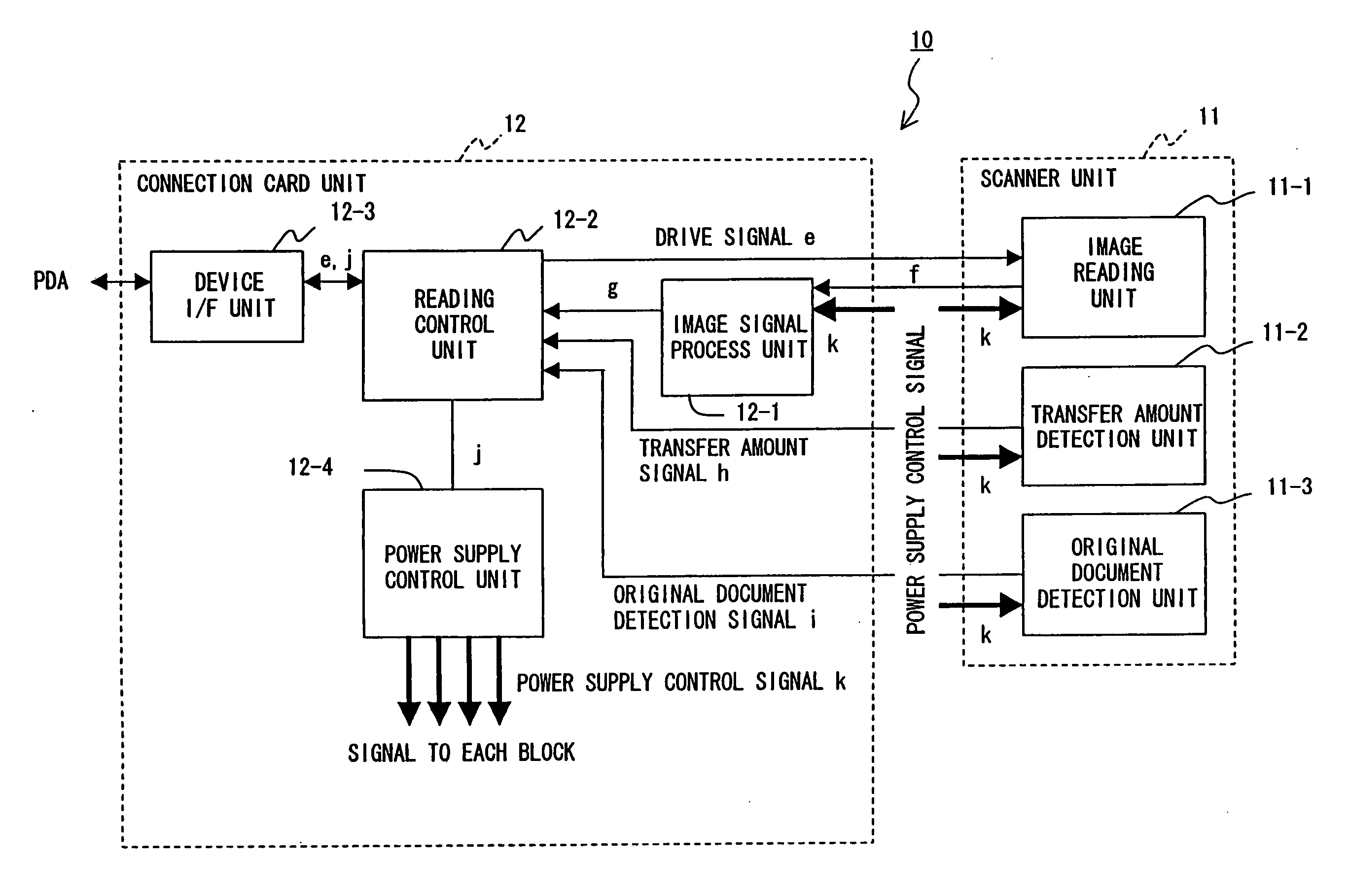
[0062]FIG. 5 is a block diagram of the function of the image reading apparatus 10 according to the Also in FIG. 5, the function blocks relating to the similar functions to the those of the hardware configuration shown in FIG. 3A are assigned the reference numerals corresponding to those assigned in the hardware configuration shown in FIG. 3A.
[0063] As shown in FIG. 5, the function block of the image reading apparatus 10 comprises an image reading unit 11-1 of the scanner unit 11, a transfer amount detection unit 11-2, an original document detection unit 11-3, an image signal process unit 12-1 of the connection card unit 12, a reading control unit 12-2 as a read control device, a device I / F unit 12-3, and a power supply control unit 12-4. Actually, the scanner unit 11 also comprises an image signal process unit functioning in conjunction with the image signal process unit 12-1 of the connection card unit 12, but they are shown in FIG. 5 as included in the image signal process unit 1...
third embodiment
[0075]FIG. 7 is a block diagram showing the function of the image reading apparatus 10 according to the Also in FIG. 7, the function blocks relating to the similar functions to the those of the hardware configuration shown in FIG. 3A are assigned the reference numerals corresponding to those assigned in the hardware configuration shown in FIG. 3A.
[0076] Furthermore, in FIG. 7, the power supply control unit 12-4 of the function block in FIG. 5 is replaced with a clock control unit 12-5, and a clock signal m transmitted from the clock control unit 12-5 to each function block is controlled depending on the image reading state.
[0077] The processing operations are almost the same except that the power supply control unit 12-4, the power supply control signal k, and the power supply shown in FIGS. 5 and 6 are respectively replaced with the clock control unit 12-5, the clock signal m, and the supply of a clock signal.
[0078] Thus, by controlling a clock signal to be supplied to each func...
PUM
 Abstract
Description
Claims
Application Information
 - R&D
- Intellectual Property
- Life Sciences
- Materials
- Tech Scout
- Unparalleled Data Quality
- Higher Quality Content
- 60% Fewer Hallucinations
Browse by: Latest US Patents, China's latest patents, Technical Efficacy Thesaurus, Application Domain, Technology Topic, Popular Technical Reports.
© 2025 PatSnap. All rights reserved.Legal|Privacy policy|Modern Slavery Act Transparency Statement|Sitemap|About US| Contact US: help@patsnap.com


