Failure monitor for motor drive control system

a failure monitor and control system technology, applied in the direction of testing/calibration of speed/acceleration/shock measurement devices, non-deflectable wheel steering, underwater vessels, etc., can solve the problem that either one of the motor angular position sensor and the output shaft angular position sensor is failing

Active Publication Date: 2005-07-21
DENSO CORP
View PDF15 Cites 48 Cited by
  • Summary
  • Abstract
  • Description
  • Claims
  • Application Information

AI Technical Summary

Benefits of technology

[0011] It is therefore a principal object of the...

Problems solved by technology

If they mismatch each other, there is a possibility that either one of the mo...

Method used


Image

  • Failure monitor for motor drive control system
  • Failure monitor for motor drive control system
  • Failure monitor for motor drive control system

Examples


first embodiment

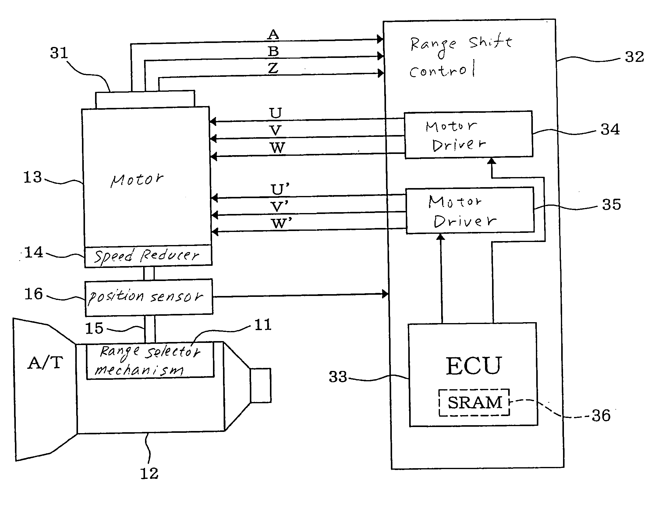
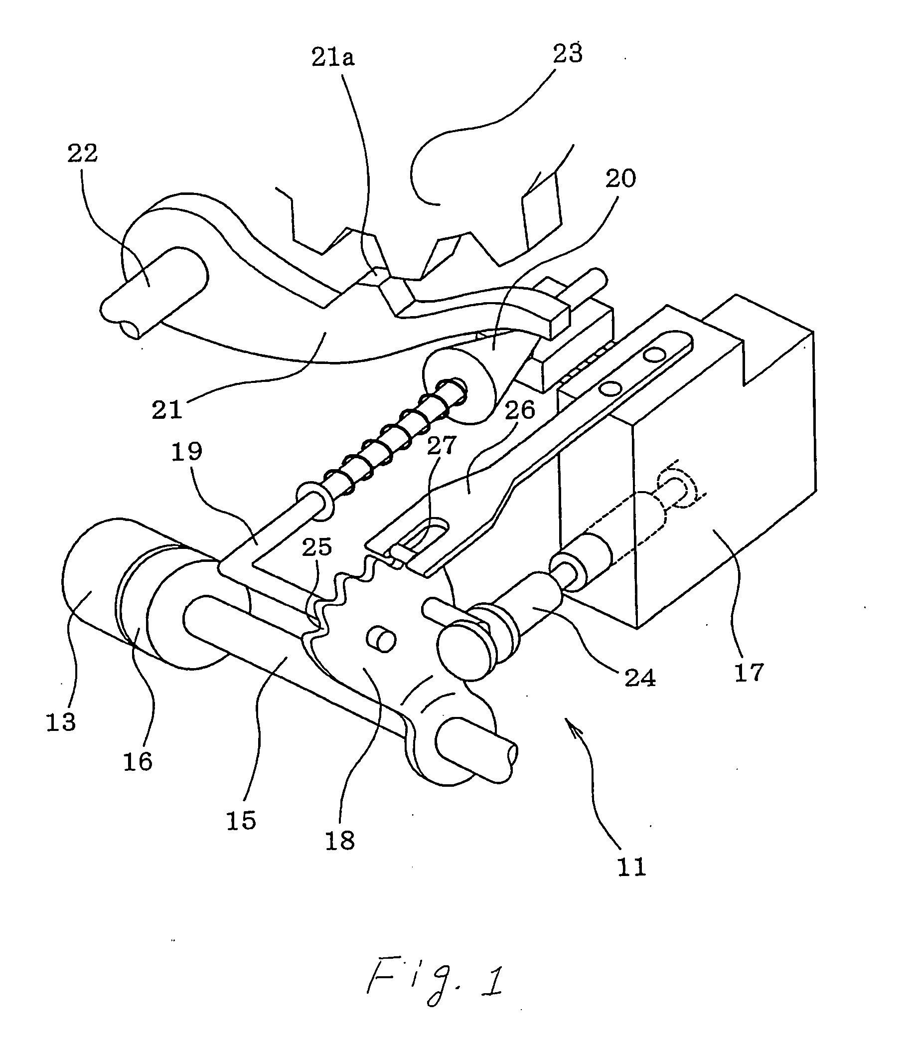
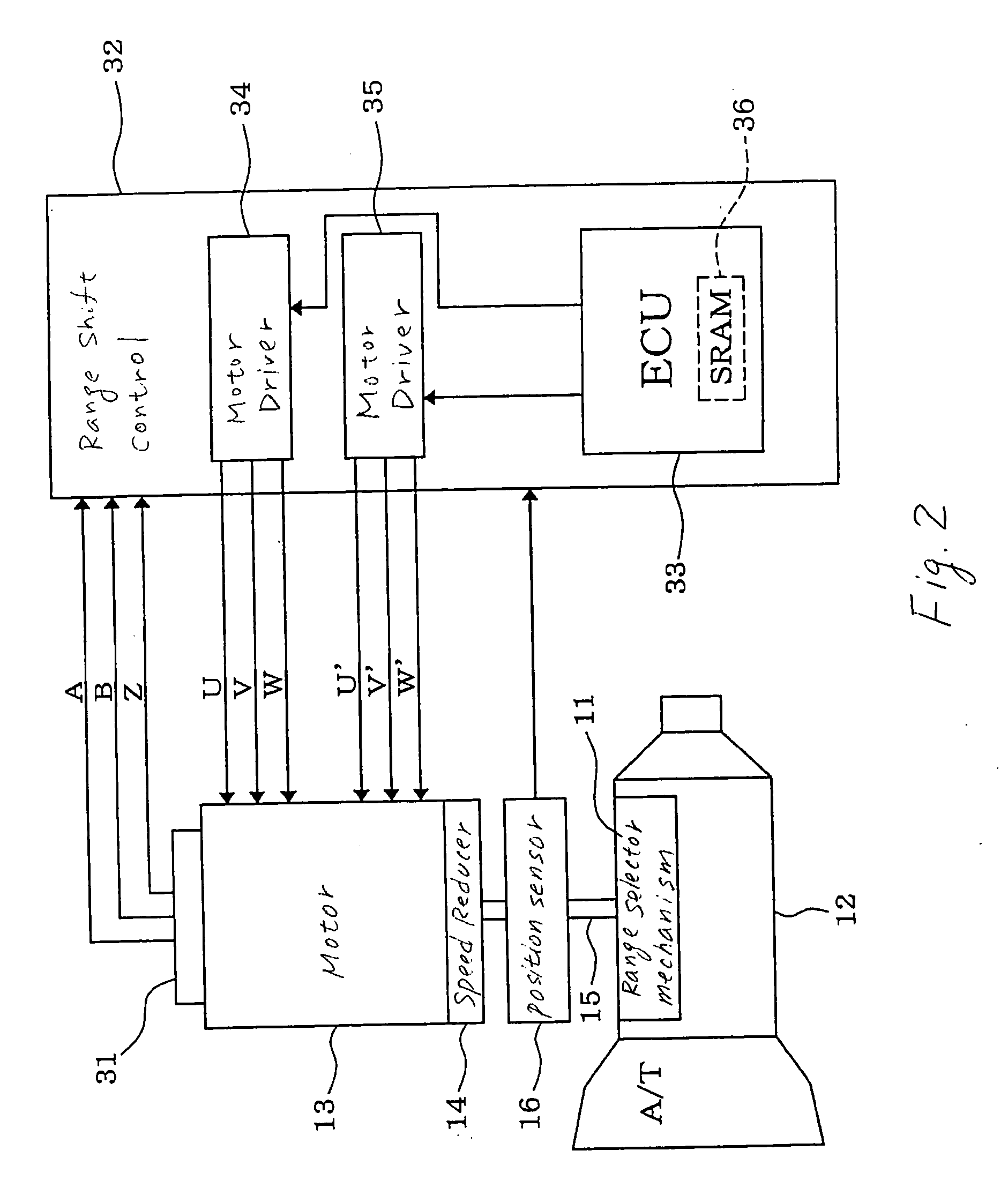
[0028] Referring to the drawings, wherein like reference numbers refer to like parts in several views, particularly to FIGS. 1, 2, and 3, there is shown a motor drive control system failure monitoring apparatus according to the invention which is used, as an example, to monitor a failure in operation of a motor drive system for a range shift mechanism11 working to change the gear of an automatic transmission 12 for automotive vehicles.

[0029] The automatic transmission 12, as referred to therein, has a typical structure which is designed to be switchable in operation between four gear ranges: a parking (P) range, a reverse (R) range, a neutral (N) range, and a drive (D) range. The range shift mechanism 11 works to shift the P, R, N, and D ranges of the automatic transmission 12 from one to another. The range shift mechanism 11 is driven by an electric motor 13. The motor 13 is made of a synchronous motor such as a switched reluctance motor (SRM) and has a speed reducing mechanism 14 ...

second embodiment

[0060] The output shaft sensor 16, as used in the second embodiment, consists, as shown in FIGS. 4 and 5, of four switches Psw, Rsw, Nsw, and Dsw each of which is turned on to produce an on-signal when the output shaft 15 falls, as can be seen in FIG. 5, in a corresponding one of four angular ranges P, R, N, and D matching the P, R, N, and D ranges of the automatic transmission 12. Specifically, the switches Psw, Rsw, Nsw, and Dsw work to produce patterns of combinations of on / off binary signals, as can be seen from FIG. 4, different among the angular ranges P, R, N, and D, thereby indicating in which of the four angular ranges P, R, N, and D the output shaft 15 is placed.

[0061]FIG. 6 shows a failure monitoring program, as executed in the ECU 33, which is different only in step 101a from the one in FIG. 3. Other steps are identical, and explanation thereof in detail will be omitted here.

[0062] The program is executed in a cycle during the on-state of the ignition switch of the vehi...


PUM


Abstract

A failure monitor designed to monitor a failure in operation of a motor drive control system. The system works to drive a motor-driven member through an output shaft and an electric motor and includes an output shaft angular position sensor for determining an angular position of the output shaft and an encoder for determining an angular position of the motor for use in controlling the motor. The system works to discriminate among failures in operation of the output shaft angular position sensor and the encoder and another type of a failure using outputs of the sensors.

Description

CROSS REFERENCE TO RELATED DOCUMENT [0001] The present application claims the benefit of Japanese Patent Application No. 2003-425925 filed on Dec. 22, 2003, the disclosure of which is incorporated herein by reference. BACKGROUND OF THE INVENTION [0002] 1. Technical Field of the Invention [0003] The present invention relates generally to a failure monitor for a motor drive control system which controls rotation of a motor working to output torque to a motor-driven member through a torque transmitting mechanism and an output shaft joined to the motor-driven member. [0004] 2. Background Art [0005] In recent years, in order to meet space saving requirements, facilitating ease of assembly, or improving controllability of automotive vehicles, there have been increased trends toward use of an electrical system working to drive a controlled mechanism through an electric motor. For example, Japanese Patent First Publication No. 2002-323127 discloses an automatic transmission control system d...

Claims


Application Information

Patent Timeline
IPC IPC(8): F16H61/28G01B21/22F16H61/32H02P3/08H02P5/747H02P6/06H02P6/08H02P6/12H02P7/00H02P25/08H02P29/02
CPCF16H61/12F16H61/32F16H2061/1208F16H2061/326H02P25/08F16H2061/1288H02P5/747
Inventor KAMIO, SHIGERUNAKAI, YASUHIRO
Owner DENSO CORP
Why Eureka
Try Eureka