Method for fabricating an enlarged fluid chamber
a technology of fluid chamber and fluid injection, which is applied in the direction of printing, etc., can solve the problems of hydraulic crosstalk and difficult droplet volume control, and achieve the effect of improving printing resolution
- Summary
- Abstract
- Description
- Claims
- Application Information
AI Technical Summary
Benefits of technology
Problems solved by technology
Method used
Image
Examples
first embodiment
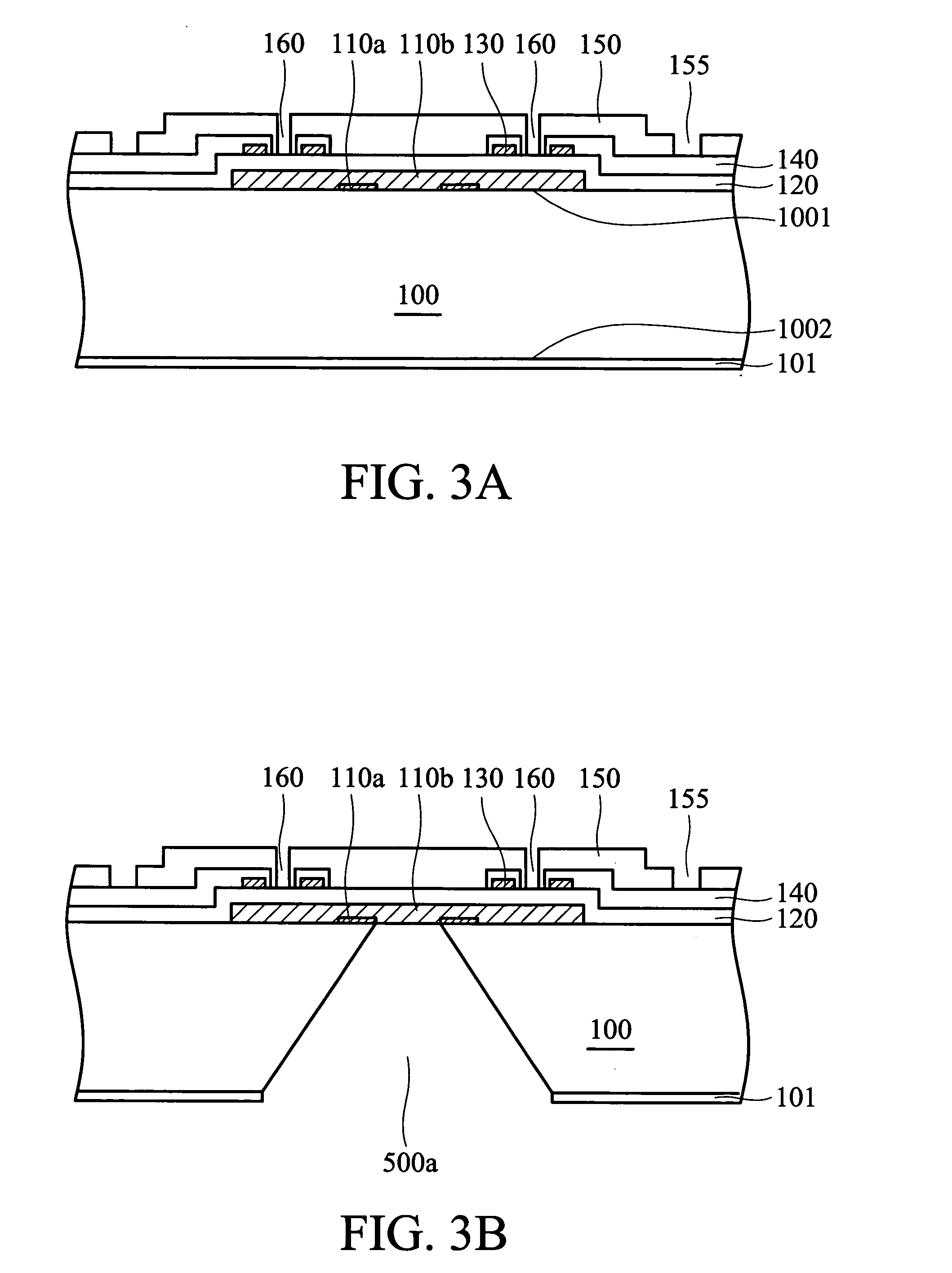
[0023]FIGS. 3A-3E are schematic views of a method for manufacturing a fluid injector in accordance with a first embodiment of the present invention using multiple sacrificial layers with different etching rates to create a chamber neck between an enlarged fluid chamber and a fluid channel. The chamber neck can stabilize ejection of the fluid droplet.
[0024] Referring to FIG. 3A, a substrate 100, such as a single crystal silicon wafer, having a first surface 1001 and a second surface 1002 is provided. A patterned first sacrificial layer 110a is formed on the first surface 1101 of the silicon substrate 100. A patterned second sacrificial layer 110b is then formed overlying the first surface 1101 of the silicon substrate 100 covering the first sacrificial layer 110a. The first sacrificial layer 110a is formed at both sides of the fluid channel with a thickness less than the second sacrificial layer 110b. The first sacrificial layer 110a comprises chemical vapor deposition of silicon ni...
second embodiment
[0034]FIGS. 4A-4E are schematic views of a method for manufacturing a fluid injector in accordance with a second embodiment of the present invention using multiple sacrificial layers with different etching rates to create a slant adjacent to the fluid channel to impede backfill of the fluid and prevent perturbation in neighboring chambers, thereby stabilizing ejection of the fluid droplet.
[0035] Referring to FIG. 4A, a substrate 100, such as a single crystal silicon wafer, having a first surface 1001 and a second surface 1002 is provided. A patterned first sacrificial layer 110a is formed on the first surface 1101 of the silicon substrate 100. The first sacrificial layer 110c is formed at one side of the fluid channel and patterned into a plurality of areas with increasing width and gaps. A patterned second sacrificial layer 110b is then formed overlying the first surface 1101 of the silicon substrate 100 covering the first sacrificial layer 110c. The thickness of the first sacrifi...
third embodiment
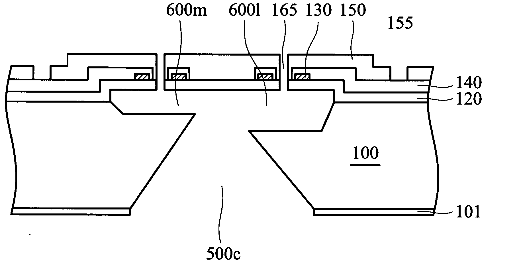
[0044]FIGS. 5A-5E are schematic views of a method for manufacturing a fluid injector in accordance with a third embodiment of the present invention using multiple sacrificial layers with different etching rates to create a single print-head chip with different chamber sizes, thereby ejecting droplets with different sizes and improving printing resolution.
[0045] Referring to FIG. 5A, a substrate 100, such as a single crystal silicon wafer, having a first surface 1001 and a second surface 1002 is provided. A patterned first sacrificial layer 110d is formed on the first surface 1101 of the silicon substrate 100. A patterned second sacrificial layer 110b is then formed overlying the first surface 1101 of the silicon substrate 100 covering the first sacrificial layer 110d. The first sacrificial layer 110d is formed at one side of the fluid channel with a thickness less than the second sacrificial layer 110b. The first sacrificial layer 110d comprises chemical vapor deposition of silicon...
PUM
 Abstract
Description
Claims
Application Information
 - R&D
- Intellectual Property
- Life Sciences
- Materials
- Tech Scout
- Unparalleled Data Quality
- Higher Quality Content
- 60% Fewer Hallucinations
Browse by: Latest US Patents, China's latest patents, Technical Efficacy Thesaurus, Application Domain, Technology Topic, Popular Technical Reports.
© 2025 PatSnap. All rights reserved.Legal|Privacy policy|Modern Slavery Act Transparency Statement|Sitemap|About US| Contact US: help@patsnap.com


