Optical converter module for display system

a technology of optical converter and display system, which is applied in the field of optical converter modules, can solve the problems of adversely affecting the service life of light sources, high thermal and electrical loads, etc., and achieve the effect of improving the brightness of liquid crystal display systems

Inactive Publication Date: 2005-07-21
AU OPTRONICS CORP
View PDF2 Cites 14 Cited by
  • Summary
  • Abstract
  • Description
  • Claims
  • Application Information

AI Technical Summary

Benefits of technology

[0007] The present application describes a system and method for converting randomly polarized light into linearly polarized light without absorption loss to improve the brightness of a liquid crystal display system. According one embodiment, the liquid crystal display system includ

Problems solved by technology

However, this increases the power consumption of the display system 100 resulting in a higher t

Method used


Image

  • Optical converter module for display system
  • Optical converter module for display system
  • Optical converter module for display system

Examples


Embodiment Construction

)

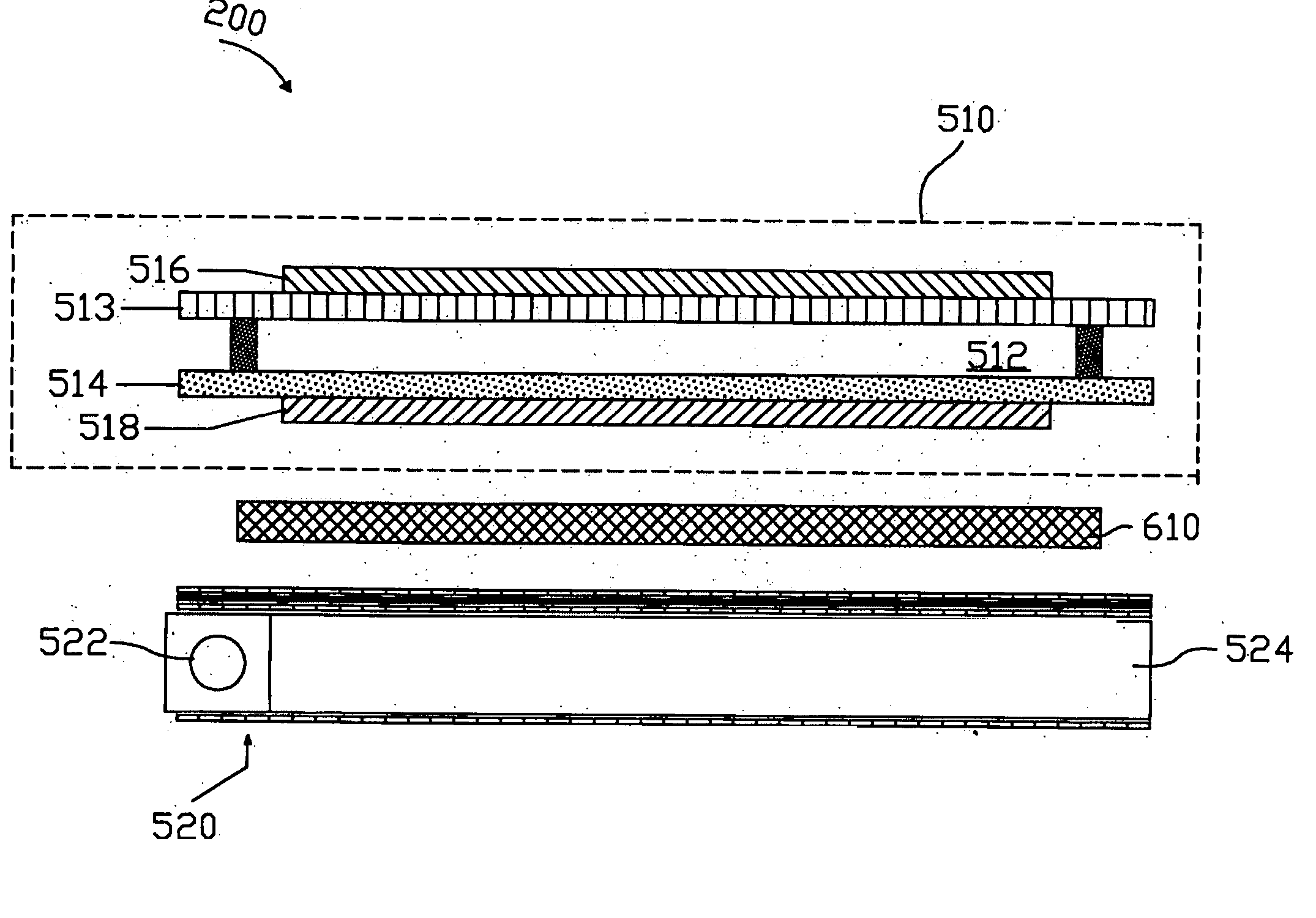
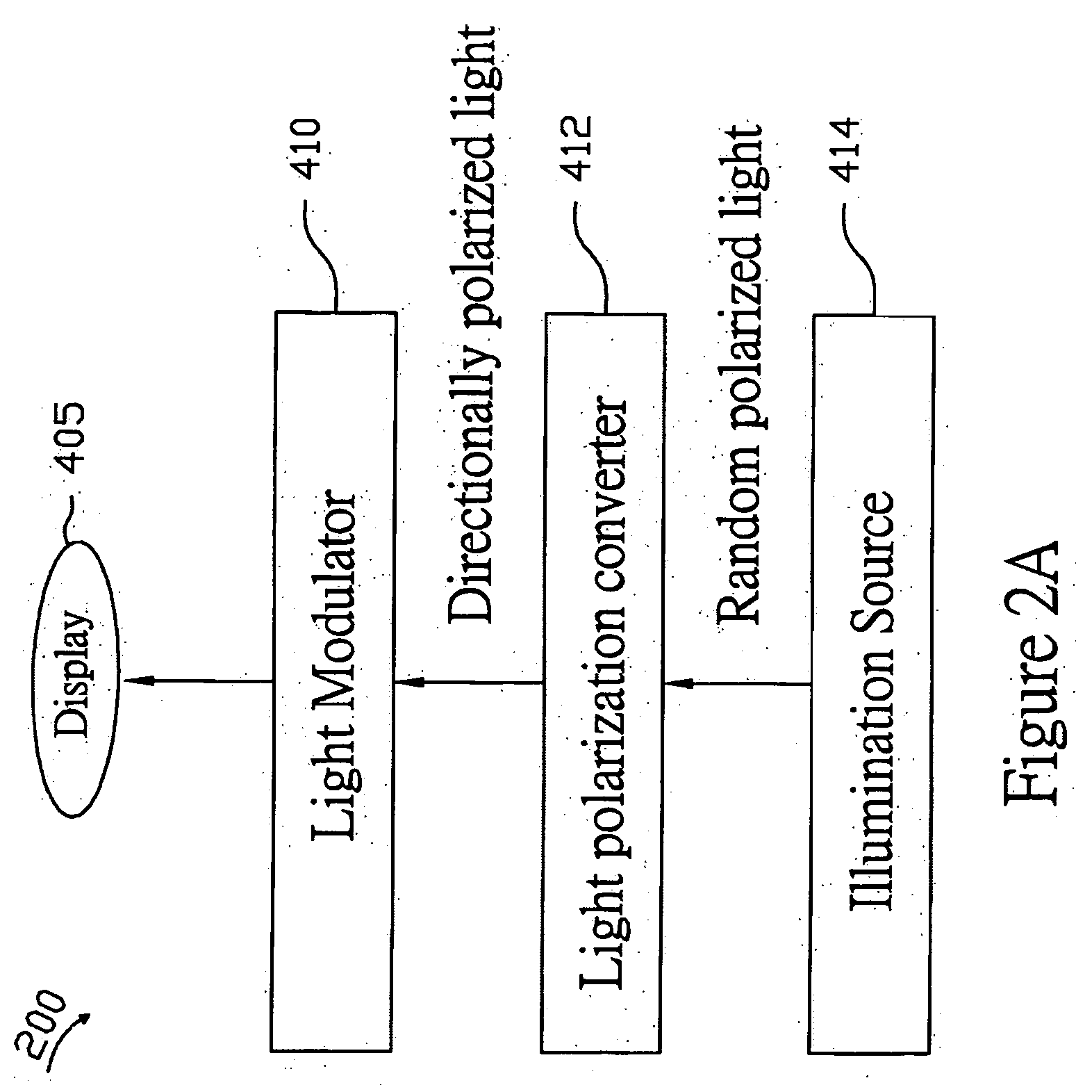
[0018]FIG. 2A is a functional block diagram of an exemplary display system 200 according to one embodiment. The display system 200 includes an illumination source 414. In the present example, the illumination source is configured to generate randomly polarized light; however, the illumination source 414 can be configured to generate unpolarized light. When the illumination source 414 is configured to generate unpolarized light, one or more polarizers can be used to convert the unpolarized light into randomly polarized light. A light polarization converter 412 is coupled to the illumination source 414. The light polarization converter 412 is configured to convert the randomly polarized light of the illumination source 414 into linearly polarized light. A light modulator 410 is coupled to the light polarization converter 412. The light modulator 410 is configured to modulate the linearly polarized light for displaying images on a display 405. In the present example, the display 405 i...


PUM


Abstract

The present application describes a system and method for converting randomly polarized light into linearly polarized light without absorption loss to improve the brightness of a liquid crystal display system. According one embodiment, the liquid crystal display system includes an optical converter module configured to convert the randomly polarized light into linearly polarized light. The optical converter module is configured to convert the polarization of a first polarized component of the randomly polarized light to be substantially similar to a second polarized component. The optical converter module transmits the first and second polarized components having substantially similar polarization.

Description

FIELD OF THE INVENTION [0001] The present invention generally relates to display systems, and more particularly, to an optical module for converting light polarization in a display system. DESCRIPTION OF THE RELATED ART [0002]FIG. 1 is a schematic view of a conventional liquid crystal display system 100. The system 100 includes a liquid crystal panel 110 and a backlight source 120 placed behind the liquid crystal panel 110. The liquid crystal panel 110 controls the passage of an input light 125 emitted from the backlight source 120. The input light 125 is randomly polarized. The liquid crystal panel 110 includes a liquid crystal layer 112 sandwiched between a front substrate 113 and a rear substrate 114. The front and rear substrates 113 and 114 are transparent substrates. The front substrate 113 can include color filters. A polarizer 116 is coupled to the front substrate 113. The rear substrate 114 includes thin-film transistor elements (not shown) that are configured to apply an e...

Claims


Application Information

Patent Timeline
IPC IPC(8): G02B5/30G02B5/04G02B27/00G02B27/28G02F1/13G02F1/1335G02F1/13357
CPCG02F1/13362G02B27/28
Inventor WU, MENG-CHAIYU, CHUAN-PEI
Owner AU OPTRONICS CORP
Why Eureka
Try Eureka