Switch apparatus and mobile communications terminal apparatus

a technology of mobile communication terminal and switch, which is applied in the direction of electrical equipment, telephonic communication, substation equipment, etc., can solve the problems of increasing increasing the cost, and increasing the probability of signal distortion during transmission, so as to prevent the occurrence of distortion and increase the size of the switch

Inactive Publication Date: 2005-07-21
SONY CORP
View PDF3 Cites 5 Cited by
  • Summary
  • Abstract
  • Description
  • Claims
  • Application Information

AI Technical Summary

Benefits of technology

[0014] As described above, in handling signals of at least three frequency bands, first, a signal of one frequency band and signals of other frequency bands are divided, and the signal in which signals of several frequency bands coexist are handled with at least three switching means in the second high-frequency switch, without increasing the size of the diplexer. The second high-frequency switch comprising at least the three switching means can be made a simple circuit configuration employing a relatively sma

Problems solved by technology

Because UMTS needs to operate as a mobile terminal of a multi-system with differing frequency bands as well as communications schemes, the circuitry thereof becomes complex, and the increase in the number of components causes the apparatus to become larger and an increase in cost.
In particular, since facilitating the sharing of an antenna, which is large in size, greatly contributes to the miniaturization of a terminal, the development of a small-sized switch apparatus is now an important issue in order to switch an antenna between systems.
In general, in handling large power with a PIN diode, there is a higher probability of causing distortion in signals during transmission when it is in the off state.
However, in order to make it possible to switch between WCDMA in addition to GSM and DCS, because WCDMA is in th

Method used


Image

  • Switch apparatus and mobile communications terminal apparatus
  • Switch apparatus and mobile communications terminal apparatus
  • Switch apparatus and mobile communications terminal apparatus

Examples


Embodiment Construction

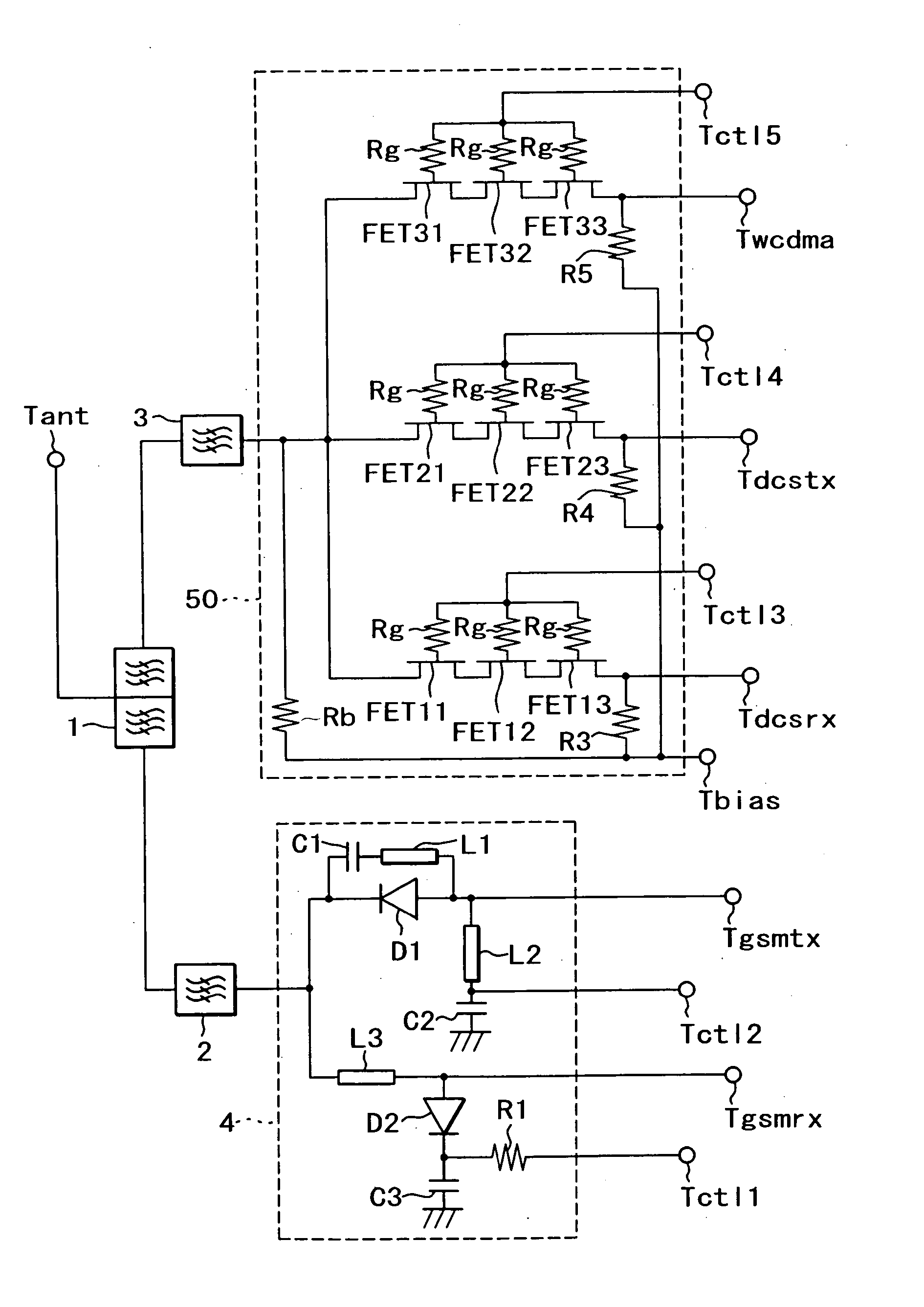
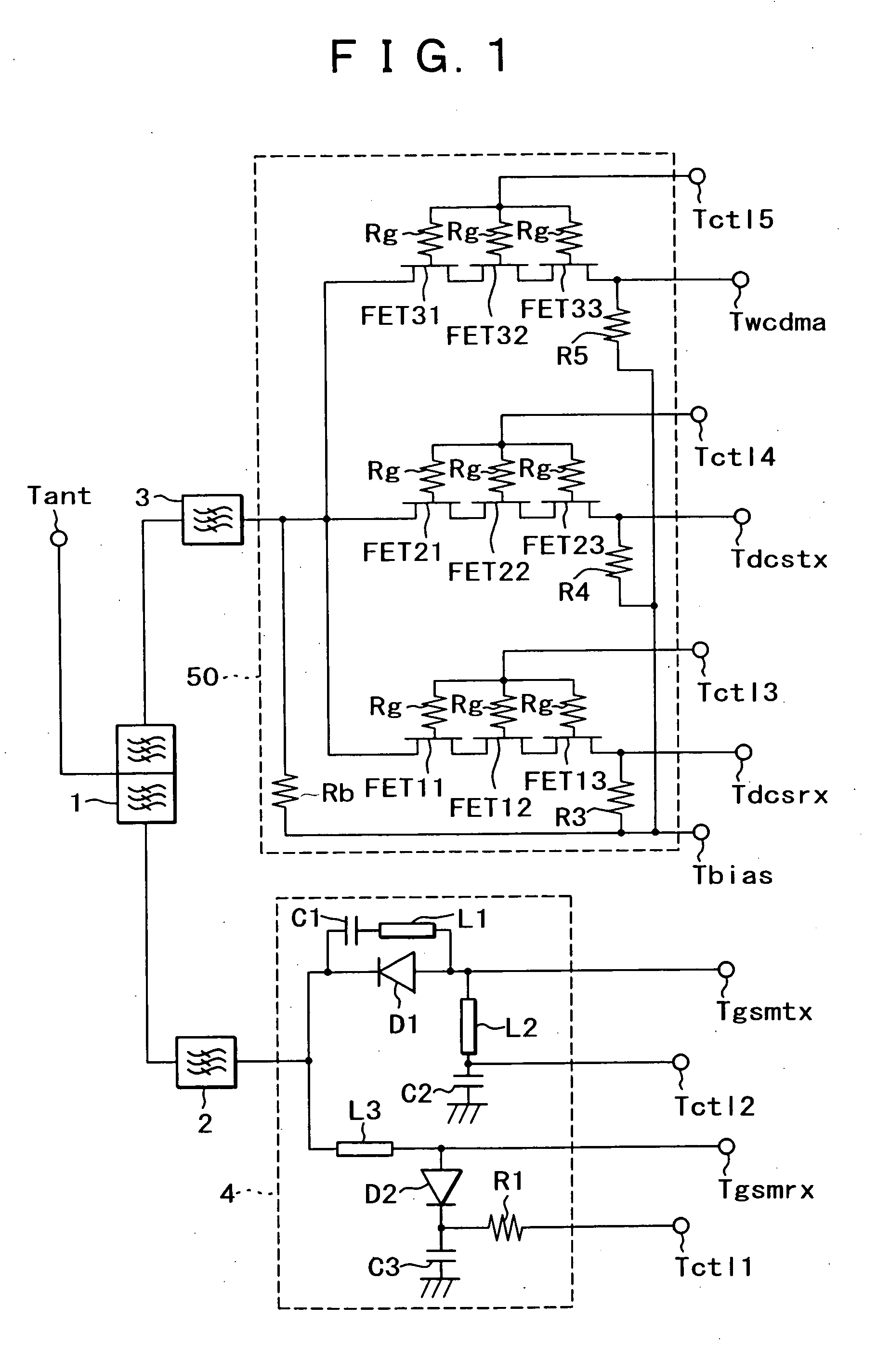
[0023] Modes for carrying out the present invention will now be described in detail below.

[0024]FIG. 1 shows the configuration of a switch apparatus of one mode for carrying out the present invention. In this drawing, like elements shown in FIG. 4 are designated by like reference numerals. An antenna, which resonates with the frequency bands of WCDMA, DCS and GSM, is connected to an antenna terminal Tant. A GSM reception circuit is connected to a GSM reception signal terminal Tgsmrx. A GSM transmission circuit is connected to a GSM transmission signal terminal Tgsmtx. A DCS reception circuit is connected to a DCS reception signal terminal Tdcsrx. A DCS transmission circuit is connected to a DCS transmission signal terminal Tdcstx. A WCDMA transmission / reception circuit is connected to a WCDMA transmission / reception signal terminal Twcdma. The reason only WCDMA is transmission / reception is because transmission and reception are simultaneously performed since the duplex operation sch...


PUM


Abstract

A small-sized switch apparatus for switching between signal paths of at least first, second and third frequency bands is capable of handling high-powered high-frequency signals with a relatively low control voltage and is useful in a mobile terminal apparatus. A first signal terminal of a diplexer is connected to an antenna terminal, and a second signal terminal is connected to a high-frequency switch via a filter. A third signal terminal of the diplexer is connected to a high-frequency switch via a second filter. The high-frequency switch has PIN diodes as switching devices, and performs switching between a global system for mobile communications transmission signal and a global system for mobile communications reception signal. The high-frequency switch has three sets of serially connected multi-staged FETs as switching devices, and performs switching between wide-band code division multiple access transmission/reception signals, a digital cellular system transmission signal and a digital cellular system reception signal.

Description

TECHNICAL FIELD [0001] The present invention relates to a mobile communications terminal apparatus, and more specifically, to a switch apparatus for use in a mobile communications terminal apparatus for a multi-system, in which various frequency bands and communications schemes are used, and for switching between signal paths of at least three frequency bands. BACKGROUND ART [0002] In recent years, mobile communications has developed significantly, and in Europe, mobile communications terminal apparatuses (hereinafter referred to simply as mobile terminals) using several frequency bands and several communications schemes are proposed. For instance, there is UMTS (Universal Mobile Telecommunication System) which combines GSM (Global System for Mobile Communications) using a frequency band of 900 MHz band, DCS (Digital Cellular System) using a frequency band of 1.8 GHz and WCDMA (Wideband Code Division Multiple Access) using a frequency band of 2 GHz. [0003] Because UMTS needs to oper...

Claims


Application Information

Patent Timeline
IPC IPC(8): H01P1/15H04B1/3822H04B1/40H04B1/48
CPCH04B1/005H04B1/48H04B1/406H04B1/006
Inventor IIDA, SACHIO
Owner SONY CORP
Why Eureka
Try Eureka