
Bone-tendon-bone implant

a technology of bone tendons and implants, applied in the field of bone tendons, can solve the problems of difficult processing, obtaining, and managing bone blocks, and achieve the effects of improving the quality of bone tendons and supporting the bone tendons

Inactive Publication Date: 2005-07-21
OSTEOBIOLOGICS
View PDF59 Cites 324 Cited by
  • Summary
  • Abstract
  • Description
  • Claims
  • Application Information

AI Technical Summary

Benefits of technology

[0012] The implant not only holds the graft tissue in place during healing, but also provides the necessary mechanical strength to allow the patient to recover quickly and return the injury site as close as possible to its original condition.

Problems solved by technology

These bone blocks can be difficult to procure, process, and manage to ensure adequate safety and quality.

Method used


Image

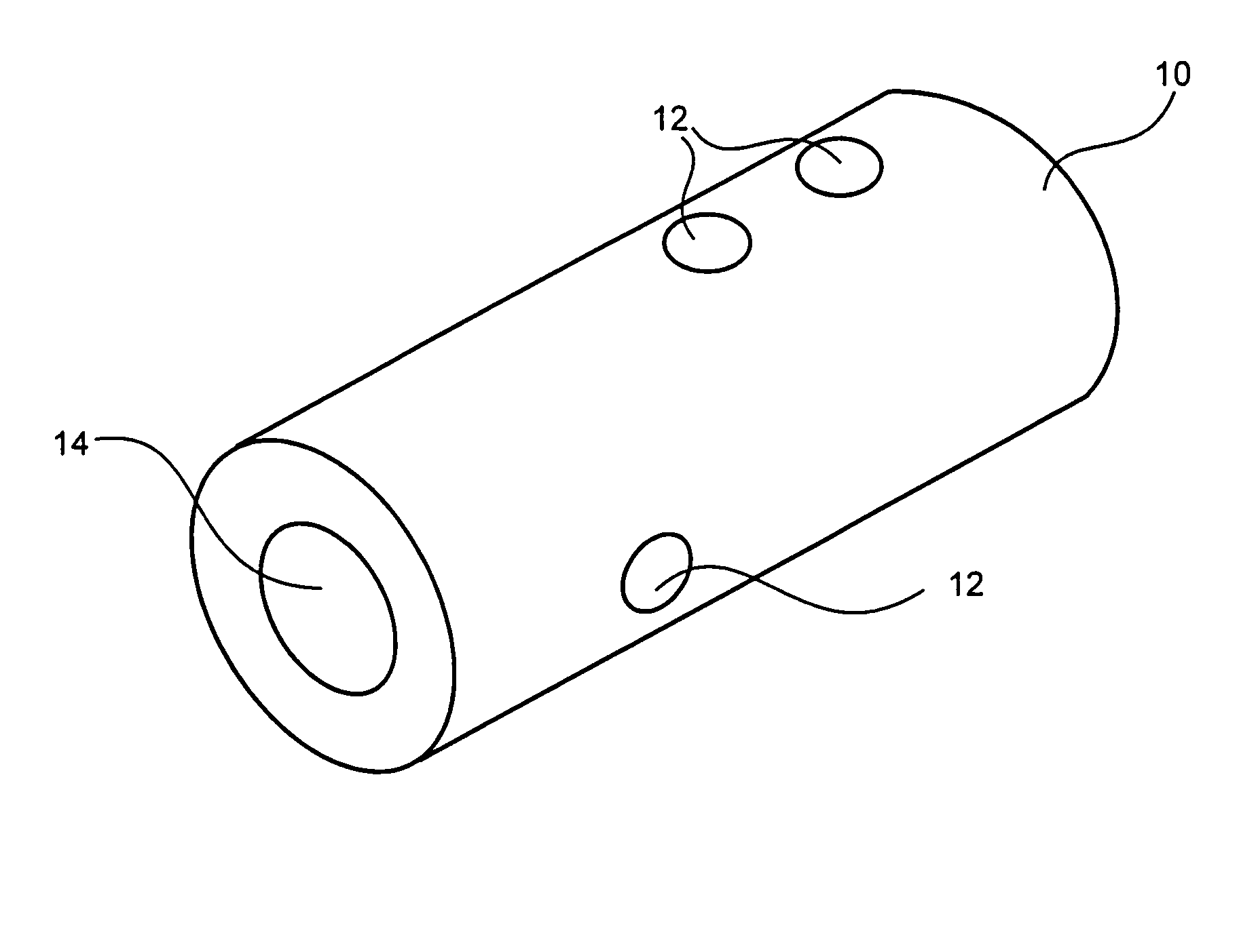
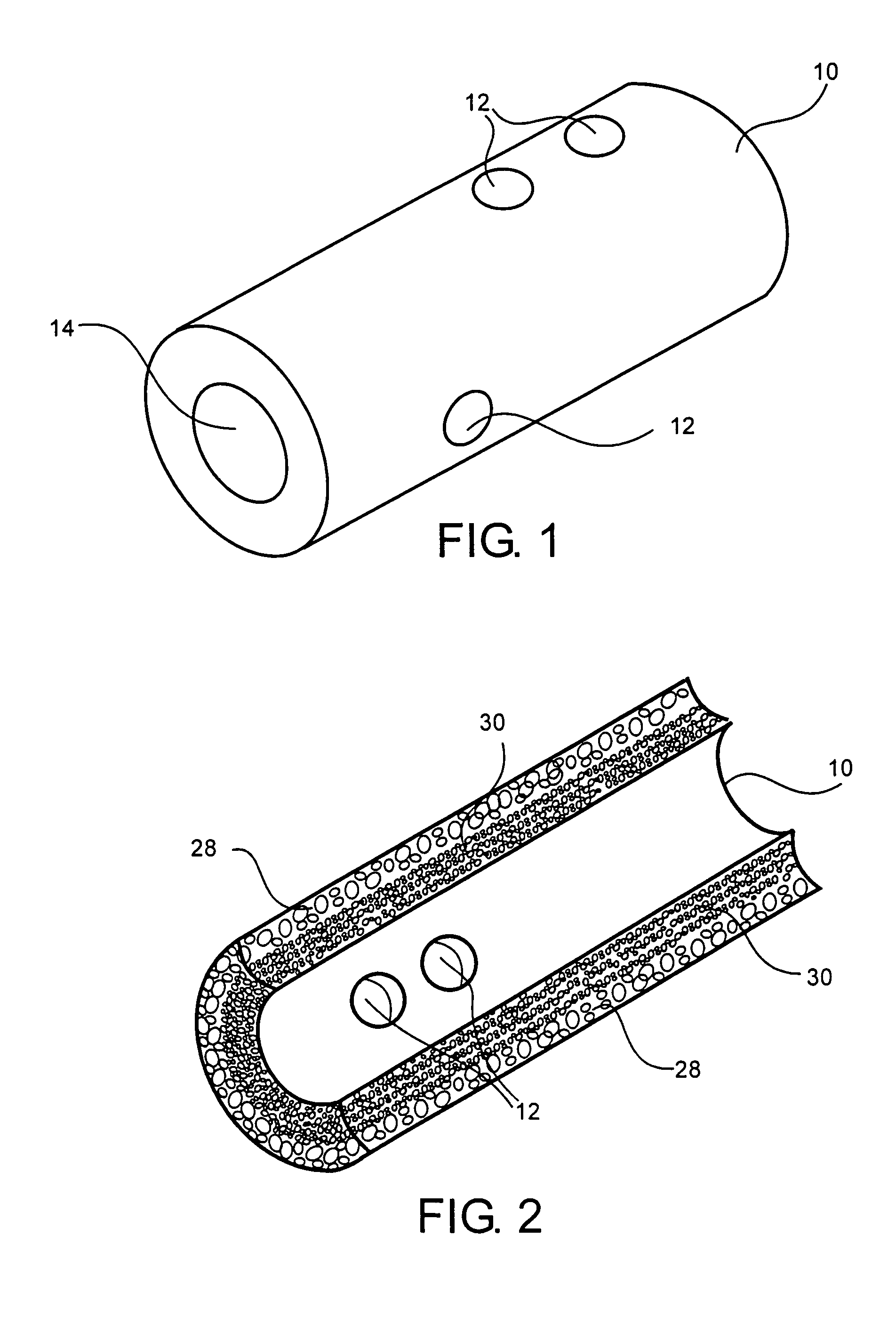
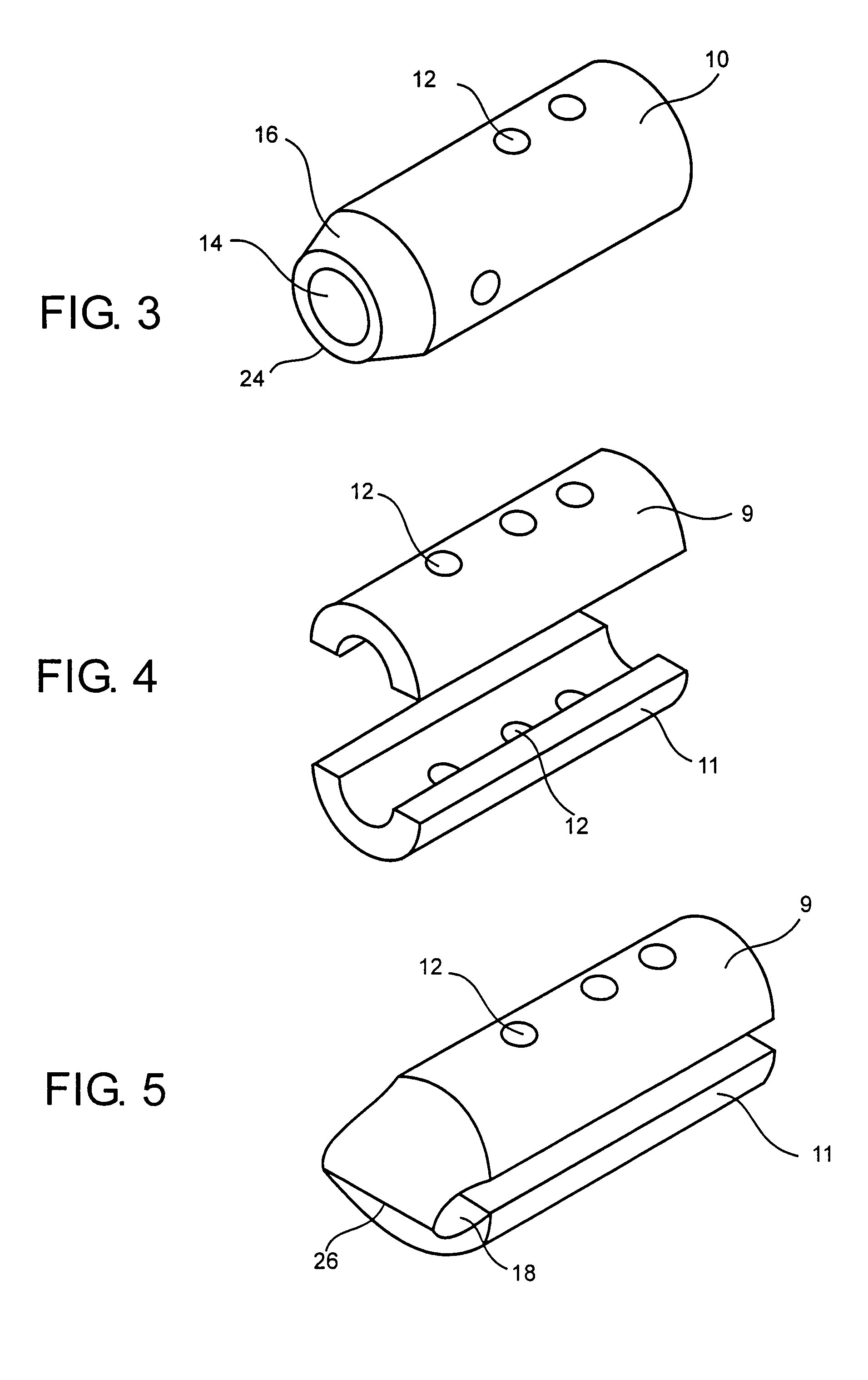
  • Bone-tendon-bone implant
  • Bone-tendon-bone implant
  • Bone-tendon-bone implant

Examples


example

[0048] BTB implants are assembled onto cadaver tibialis tendons on a graft preparation table by wrapping the tendons around the implants and securing them to the implants using No. 5 braided polyester suture. The implants are arthroscopically placed into cadaver knees using standard surgical technique, and secured in place with interference screws.

[0049] Knee samples are potted into testing fixtures using a fast-curing epoxy compound. Once the epoxy is cured, the samples are placed in a screw-type mechanical testing machine. The specimens are placed in tension until the graft construct fails. The implant graft assemblies are found to have pull-out strengths of 400 N and greater.


PUM


Abstract

An implant for repairing soft tissue injuries is provided comprising at least one channel for receiving a soft tissue graft such as a tendon, ligament, or other soft tissue, to be implanted in a patient. The implant assembled with the graft is designed to fit into a bony defect, such as a graft tunnel, formed in bone of a patient. The implant can be biodegradable, and the implant-graft assembly has a pull-out strength sufficient to withstand everyday use during patient recovery.

Description

CROSS-REFERENCE TO RELATED APPLICATION [0001] This application claims priority to U.S. Provisional Patent Application Ser. No. 60 / 537,214 filed Jan. 16, 2004, incorporated herein by reference to the extent not inconsistent herewith.BACKGROUND [0002] In high-impact sports, ligaments are often injured through twisting of the knee or through an impact to the side of the knee. Primarily, the anterior cruciate ligament (ACL) and posterior cruciate ligament (PCL) are involved. To reconstruct these ligaments, the most common method involves a bone-patellar tendon-bone (BTB) graft, which is considered the gold standard. While the BTB graft has a 90-95% success rate, one of its disadvantages is that the tendon length may not match the original length of the ACL. Other alternatives for ACL reconstruction are the use of Achilles, hamstring or tibialis soft tissue grafts, where one or two tendon strands, autograft, allograft, or xenograft, are used to reconstruct the ligament. Defects are drill...

Claims


Application Information

Patent Timeline
IPC IPC(8): A61F2/08
CPCA61F2/0811A61F2002/0835A61F2250/0023A61F2002/0864A61F2002/0888A61F2002/0852
Inventor DINGER, FRED B. IIILEE, DANIEL R.NIEDERAUER, GABRIELE G.WRANA, JEFFREY S.
Owner OSTEOBIOLOGICS
Learn More