Catalytic reactors

Inactive Publication Date: 2012-05-08
COMPACTGTL
View PDF16 Cites 5 Cited by
  • Summary
  • Abstract
  • Description
  • Claims
  • Application Information

AI Technical Summary

Benefits of technology

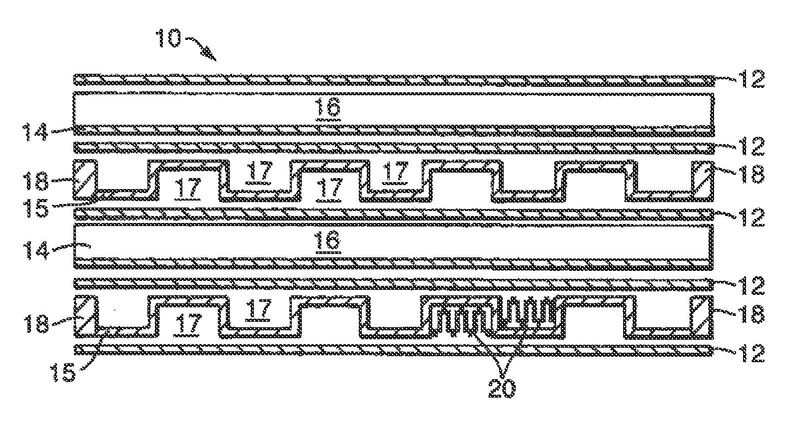
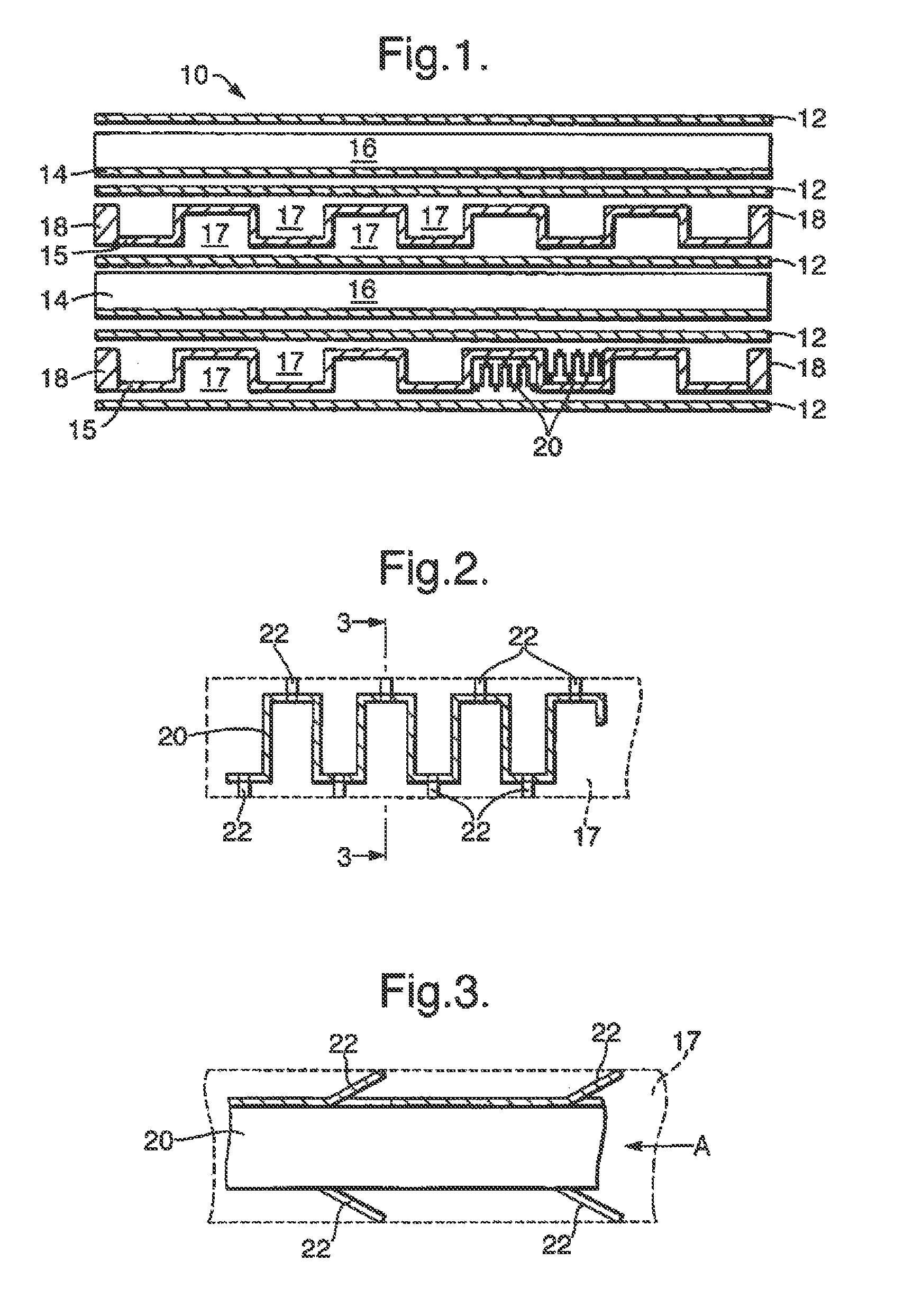
[0009]The reactor must also be provided with headers to supply the fluids to the flow channels, and preferably each first header comprises a chamber attached to the outside of the reactor and communicating with a plurality of the first flow channels, and each second header comprises a chamber attached to the outside of the reactor and communicating with a plurality of the second flow channels, such that after removal of a header, the corresponding catalyst layers in the flow channels are removable. This ensures that the catalysts can easily be replaced when they become spent.
[0010]The catalyst structure preferably incorporates a ceramic coating to carry the catalytic material. Preferably the metal substrate for the catalyst

Problems solved by technology

The catalyst structures do not provide strength to the reactor, so the reactor i

Method used


Image

  • Catalytic reactors
  • Catalytic reactors
  • Catalytic reactors

Examples


Embodiment Construction

[0026]The invention is applicable to a wide range of different chemical reactions, particularly those involving gaseous reactants and requiring a catalyst. For example it would be applicable in a chemical process for converting natural gas (primarily methane) to longer chain hydrocarbons. This can be achieved by a two-stage process, shown in FIG. 8, and each stage might use a reactor of the invention. The first stage is steam reforming, in a reactor 801, in which steam is mixed with natural gas and heated to an elevated temperature (so as to reach say 800° C.) so that reforming occurs:

H2O+CH4→CO+3H2

[0027]This reaction is endothermic, and may be catalysed by a rhodium or platinum / rhodium catalyst in a flow channel. The heat required to cause this reaction may be provided by combustion of an inflammable gas such as methane or hydrogen, which is exothermic and may be catalysed by a platinum / palladium catalyst in an adjacent second gas flow channel of the reactor 801.

[0028]The gas mixt...


PUM


Abstract

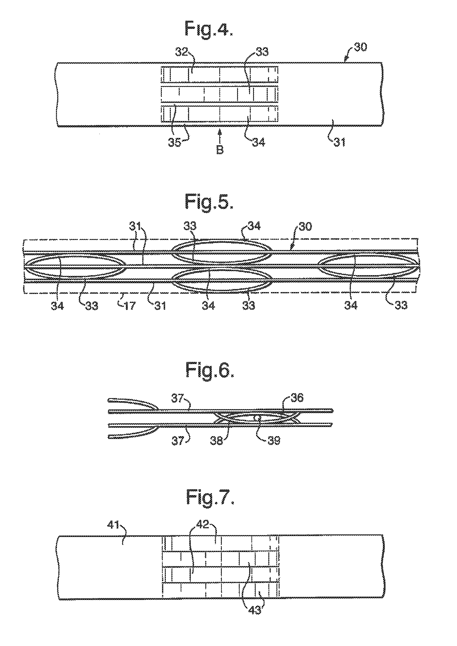
A compact catalytic reactor defines a multiplicity of first and second flow channels arranged alternately in the reactor, for carrying first and second fluids, respectively, wherein at least the first fluids undergo a chemical reaction. Each first flow channel containing a removable gas-permeable catalyst structure (20) incorporating a metal substrate, the catalyst structure defining flow paths therethrough, with catalytic material on at least some surfaces of each such path. The catalyst structure also incorporates a multiplicity of projecting resilient lugs (22) which support the catalyst structure (20) spaced away from at least one adjacent wall of the channel (17).

Description

BACKGROUND[0001]1. Field of the Invention[0002]This invention relates to a catalytic reactor suitable for use in a chemical process to convert natural gas to longer-chain hydrocarbons, and to a plant including such catalytic reactors to perform the process.[0003]2. Description of Related Art[0004]A process is described in WO 01 / 51194 and WO 03 / 033131 (Accentus plc) in which methane is reacted with steam, to generate carbon monoxide and hydrogen in a first catalytic reactor; the resulting gas mixture is then used to perform Fischer-Tropsch synthesis in a second catalytic reactor. The overall result is to convert methane to longer chain hydrocarbons of higher molecular weight, which are usually liquids or waxes under ambient conditions. The two stages of the process, steam / methane reforming and Fischer-Tropsch synthesis, require different catalysts, and catalytic reactors are described for each stage. In each case the catalyst may comprise a corrugated foil coated with catalytic mater...

Claims


Application Information

Patent Timeline
IPC IPC(8): B01J8/00B01J19/24C10G2/00
CPCB01J19/249C10G2/341B01J2219/2453B01J2219/2459B01J2219/2462B01J2219/2465B01J2219/2472B01J2219/2479B01J2219/2498C10G2300/1025
Inventor BOWE, MICHAEL JOSEPH
Owner COMPACTGTL
Why Eureka
Try Eureka