Self-spreading trawls having a high aspect ratio mouth opening

a self-spreading, trawl technology, applied in the field of trawls, can solve the problems of untargeted species being caught in conventional mid-water trawls, untargeted species being caught intermingled with one or more untargeted species, etc., and achieve the effect of reducing bycatch

Inactive Publication Date: 2005-07-28
CANDIS EHF
View PDF34 Cites 79 Cited by
  • Summary
  • Abstract
  • Description
  • Claims
  • Application Information

AI Technical Summary

Benefits of technology

[0042] An object of the present inventi...

Problems solved by technology

In the field of pelagic and semipelagic fisheries a well recognized problem exists that a targeted species is frequently intermingled with one or more untargeted species.
Thus, catching a targeted species with currently available pelagic fish nets, such as pelagic trawl nets that are also known as mid-water trawls, inadvertently results in undesired catching of non-targeted species, frequently referred to as “bycatch.
Conventional mid-water trawls, i.e. non self-spreading trawls which are in general cone-shaped and are rather long from front to rear, are substantially less effective if their design or use exhibits a wide horizontal mouth opening and a short vertical mouth opening, e.g. an opening that is 75-200% or more wider than tall.
One reason such conventional trawls are less effective if they have such a high aspect ratio mouth opening is that the relatively short vertical opening does not transfer vertically oriented opening forces well from the mouth of the trawl far back to the rear sections of the trawl.
Such compressive force occurring in the trawl's side panels tend to collapse the trawl's vertical opening in the aft section of the trawl.
In addition to the above mentioned difficulties, such contemporary conventional trawls designs are relatively expensive to manufacture because they require a comparatively large number of mesh cells and material for narrower side panels.
Furthermore, since contemporary conventional trawls lack any force which tends to actively maintain vertical opening, the trawls vertical opening tends to be lo...

Method used


Image

  • Self-spreading trawls having a high aspect ratio mouth opening
  • Self-spreading trawls having a high aspect ratio mouth opening
  • Self-spreading trawls having a high aspect ratio mouth opening

Examples


embodiment

Spread Zone Embodiment

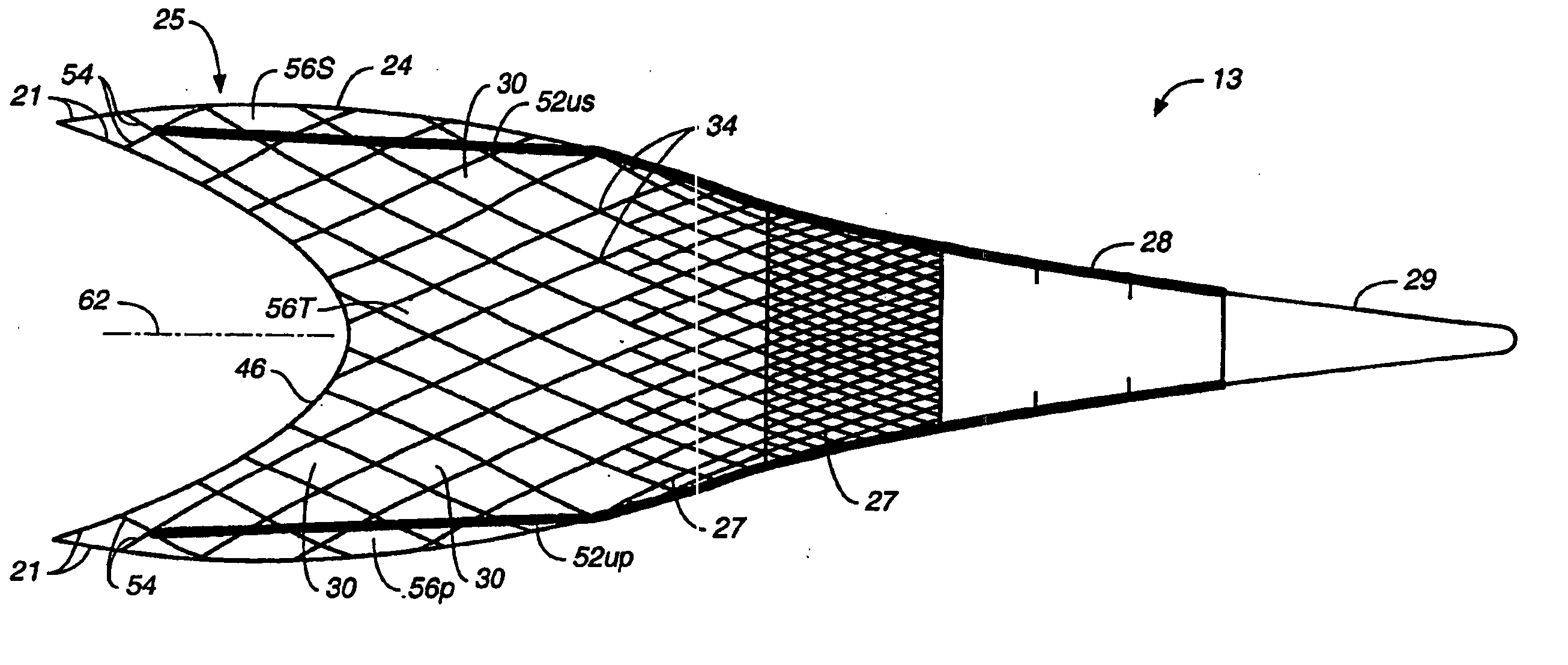
[0114] As shown in FIGS. 7, 8 and 9, the side-panels 56S, 56P of the trawls 13 built in accordance with the present invention include a mesh area that extends forward (i.e. away from the back-end 28 and nearer the vessel 10) further than corresponding mesh areas in the top panel 56T and / or bottom panel 56B. That is, the designed center of the breastlines 42, or an equivalent of the designed center of the breastlines 42, preferably projects at least one (1) full mesh length ahead of the designed center of the of the footrope 44 and / or the headrope 46. In FIGS. 7, 8 and 9, a dashed line 112 indicates the location in the side-panels 56S, 56P which has mesh cells 30 spanning completely across the side-panels 56S, 56P between the upper riblines 52up and 52us and the lower riblines 521p and 521s. The dashed line 112 is ahead of, i.e. nearer the vessel 10 than, the location in the top panel 56T and the bottom panel 56B which has mesh cells 30 spanning completely betwe...


PUM


Abstract

An improved self-spreading trawl (13) includes first panels (56T, 56B) which when towed through a body of water (12) separate on opposite sides of the trawl's central axis (62). Portions of panels (56T, 56B) form portions of the trawl's mouth (26). The trawl (13) also includes second panels (56P, 56S) which separate on opposite sides of the central axis (62) from the sides occupied by the panels (56T, 56B). Portions of panels (56P, 56S) form portions of the trawl's mouth (26). Regions of panels (56P, 56S) generate more outwardly directed lift than corresponding regions of the panels (56T, 56B). When towed through the body of water (12): a) a distance separating the panels (56P, 56S) exceeds; b) a distance separating the panels (56T, 56B). Also a braided product strand which includes at least 3 plaits (76, 102), at least one (76) of which is larger than the others (102), advantageously exhibits less drag and vibration.

Description

TECHNICAL FIELD [0001] The present invention relates generally to the technical field of trawls used for fishing and, more particularly, to an improved construction for self-spreading mid-water trawls. BACKGROUND ART [0002] In the field of pelagic and semipelagic fisheries a well recognized problem exists that a targeted species is frequently intermingled with one or more untargeted species. Thus, catching a targeted species with currently available pelagic fish nets, such as pelagic trawl nets that are also known as mid-water trawls, inadvertently results in undesired catching of non-targeted species, frequently referred to as “bycatch. [0003] In the North Pacific Pollock fishery, for example, the targeted species is often densely intermingled with other species. However, during many fishing conditions a comparatively thin strata of water is often substantially free of the non-targeted species, while simultaneously possessing an acceptable density of the targeted species. Directly ...

Claims


Application Information

Patent Timeline
IPC IPC(8): A01K73/02A01K73/04A01K73/045A01K1/00A01K75/00D02G3/22D04G1/00
CPCA01K73/045A01K75/00D04C1/12D04G1/00D07B2201/209D07B1/025D07B5/005D07B2201/1096D07B1/02
Inventor SAFWAT, SHERIFF ADHAMPEREVOSHCHIKOV, VALENTIN GAVRILOVICH
Owner CANDIS EHF
Why Eureka
Try Eureka