Beverage bottling plant for filling bottles with a liquid beverage having a treatment device for beverage container caps

a technology for beverage bottling and beverage container caps, which is applied in the direction of caps, liquid handling, packaging goods, etc., can solve the problems of inability to treat caps that are extremely attractive for modern industrial applications using the devices of the prior, flat caps, and the like, so as to reduce the risk of tipping and thus jamming, the effect of reducing the risk of vertical movemen

Active Publication Date: 2005-07-28
KHS GMBH
View PDF3 Cites 2 Cited by
  • Summary
  • Abstract
  • Description
  • Claims
  • Application Information

AI Technical Summary

Benefits of technology

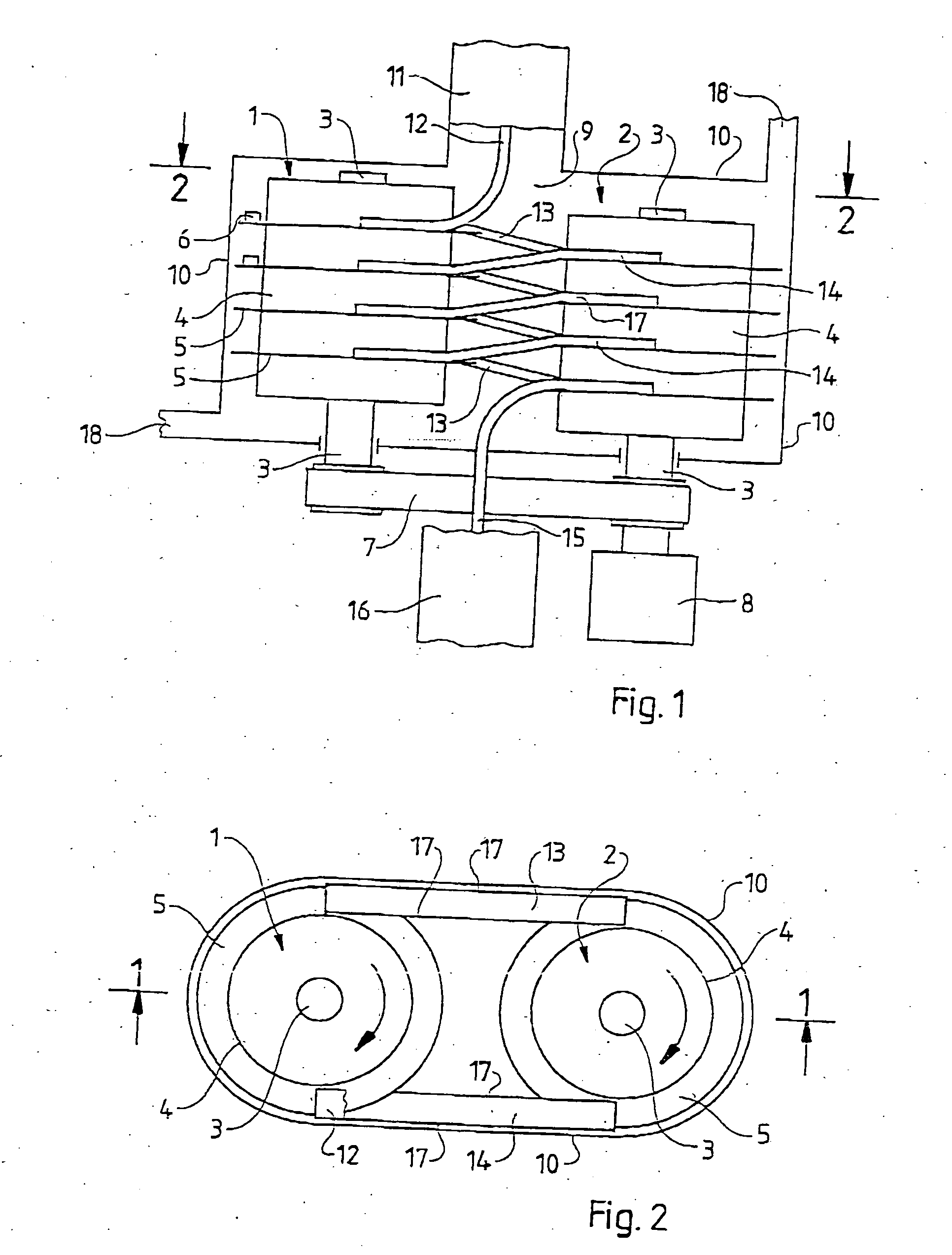
[0015] The tiers on which the carrier rings are located can be on the same level in both towers. In that case, the caps travel through a plurality of towers either on the same level, i.e. horizontally, or in a downward movement to overcome a vertical distance between tiers. Advantageously, however, an embodiment may be designed such that the tiers in the two towers may be vertically offset from each other. From each tower to the next, only a portion of the difference between tiers must be overcome, so that there may be a significantly reduced vertical movement for the transfer chutes. When there are two towers, the tiers can be advantageously vertically offset from one another by half a tier, so that each of the transfer chutes has to overcome a vertical difference of only one-half the height of a tier between the towers.
[0016] The transfer chutes can run between the towers on a curved route, when viewed from overhead, whereby the present application teaches that the radii can be significantly larger than in the prior art and thus the risk of wedging and jamming may be reduced. Advantageously, however, an embodiment may comprise a treatment device characterized by the fact that the transfer chutes are realized straight, when viewed from above. The embodiment may result in this ability, namely to connect the carrier rings of neighboring towers with transfer chutes that are completely straight when viewed from overhead, so that the risk of tipping and thus jamming may be significantly reduced.
[0017] The transfer chutes can run into the carrier rings at a slight angle, when viewed from above, as a result of which, on the path traveled by the caps, the length ratio between the distance traveled on the carrier rings and on the transfer chutes can be improved in favor of the carrier rings, i.e. the caps lie on the driving carrier rings longer. Advantageously, however, an embodiment may comprise a treatment device characterized by the fact that the carrier rings of the two towers have the same direction of rotation. As a result of the tangential inlet to the carrier rings, there may be an ideally smooth pickup of the caps from the carrier rings and an ideally smooth delivery to carrier rings. In connection with an embodiment that may comprise a treatment device characterized by the fact that the transfer chutes are realized straight, when viewed from above, the result may be a construction in which the transfer chutes can be oriented in the form of tangents to the respective connected carrier rings.
[0018] The carrier rings of the two towers can be driven in directions of rotation that are opposite to each other. When the transfer chutes have a tangential orientation, that could then cross over one another between the towers. Advantageously, however, an embodiment may comprise a treatment device characterized by the fact that the carrier rings of the two towers have the same direction of rotation. With the towers rotating in the same direction of rotation, the transfer chutes can be realized in the form of tangents laid from outside on the carrier rings, which may result in a particularly simple and reliable construction, and in particular may prevent problems with the crossover of the levels of the transfer chutes that carry the caps in opposite directions, of the type that would occur [if the towers were rotating] with opposite directions of rotation.
[0019] The carrier rings taught by the present application, because they all lie on the same path of movement of the caps, everything must be driven at the same circumferential speed. It therefore may be altogether possible, for special constructive reasons, to realize carrier rings inside a tower with a different diameter. In particular, the carrier rings of the first tower can also have a different diameter than the rings of the other tower. Advantageously, however, an embodiment may comprise a treatment device characterized by the fact that all the carrier rings have the same diameter. If all the carrier rings are the same size, the result is a particularly simple construction with interchangeable identical parts.
[0020] In the constructively simplest case, two towers stand at some distance from each other. Their center-to-center distance is thereby greater than the sum of their carrier ring radii. Advantageously, however, an embodiment may comprise a treatment device characterized by the fact that all the carrier rings have the same diameter, if the tiers of the two towers are vertically offset from one another. In that case, the carrier rings can be arranged so that they are engaged with one another and overlap laterally, whereby therefore, for each tier, the sum of the radii of the carrier rings is greater than the center-to-center distance between the two towers. The overall height of the structure can thereby be significantly reduced, and the length of the tangential transfer chutes that connect the towers can be reduced, so that for the caps, the ratio of the driven distance (on the carrier rings) to the sliding distance over which they have to be decelerated (on the transfer chutes) improves.

Problems solved by technology

The continuous stream of caps must be treated in the device for a relatively long period of time, i.e. it must travel a relatively long distance.
Therefore, some shapes of caps that are extremely attractive for modern industrial applications cannot be processed using the devices of the prior art because of the danger of jamming.
Even very flat caps, the basic shape of which is essentially that of a coin, of the type that are used, for example, as flat sealing caps underneath screw-on caps, cannot be processed, because their very low edges tend to ride over each other when they tip.
The continuous stream of caps must be treated in the device for a relatively long period of time, i.e. it must travel a relatively long distance.

Method used


Image

  • Beverage bottling plant for filling bottles with a liquid beverage having a treatment device for beverage container caps
  • Beverage bottling plant for filling bottles with a liquid beverage having a treatment device for beverage container caps
  • Beverage bottling plant for filling bottles with a liquid beverage having a treatment device for beverage container caps

Examples


Embodiment Construction

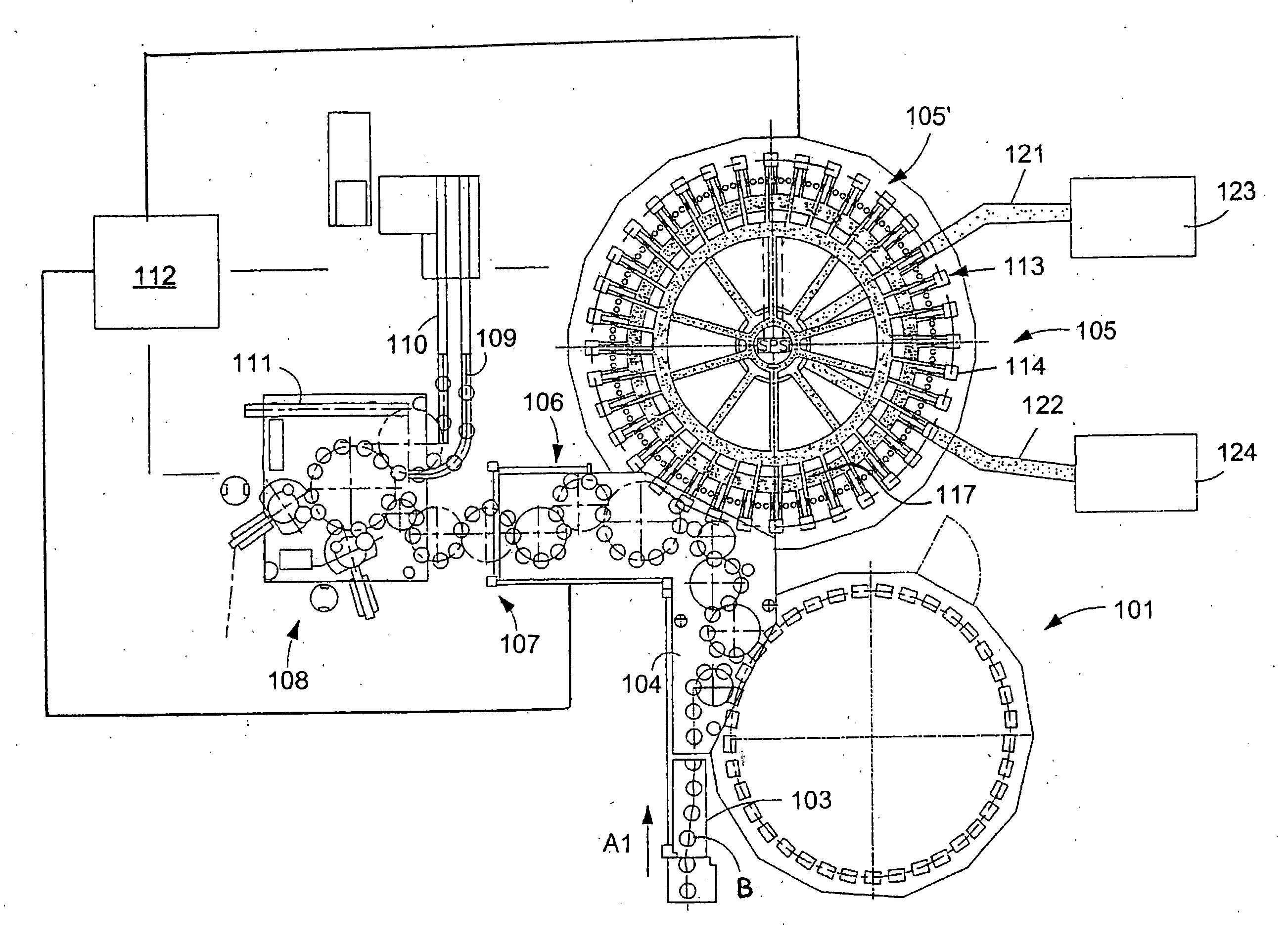
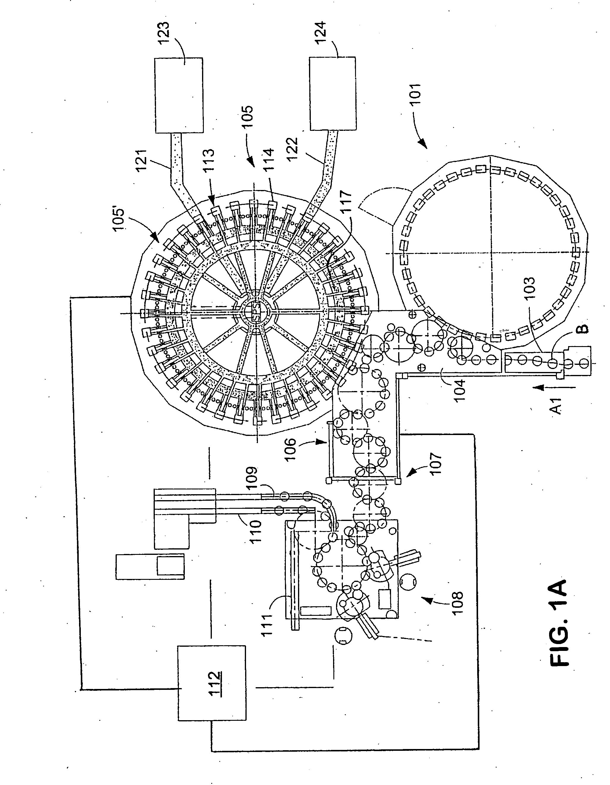
[0031]FIG. 1A shows schematically the main components of one possible embodiment example of a system for filling containers, specifically, a beverage bottling plant for filling bottles B with at least one liquid beverage, in accordance with at least one possible embodiment, in which system or plant could possibly be utilized at least one aspect, or several aspects, of the embodiments disclosed herein.

[0032]FIG. 1A shows a rinsing arrangement or rinsing station 101, to which the containers, namely bottles B, are fed in the direction of travel as indicated by the arrow A1, by a first conveyer arrangement 103, which can be a linear conveyor or a combination of a linear conveyor and a starwheel. Downstream of the rinsing arrangement or rinsing station 101, in the direction of travel as indicated by the arrow A1, the rinsed bottles B are transported to a beverage filling machine 105 by a second conveyer arrangement 104 that is formed, for example, by one or more starwheels that introduc...


PUM

PropertyMeasurementUnit
angleaaaaaaaaaa
speedaaaaaaaaaa
direction of rotationaaaaaaaaaa

Abstract

A beverage bottling plant for filling bottles with a liquid beverage having a treatment device for beverage container caps. The abstract of the disclosure is submitted herewith as required by 37 C.F.R. §1.72(b). As stated in 37 C.F.R. §1.72(b): A brief abstract of the technical disclosure in the specification must commence on a separate sheet, preferably following the claims, under the heading “Abstract of the Disclosure.” The purpose of the abstract is to enable the Patent and Trademark Office and the public generally to determine quickly from a cursory inspection the nature and gist of the technical disclosure. The abstract shall not be used for interpreting the scope of the claims. Therefore, any statements made relating to the abstract are not intended to limit the claims in any manner and should not be interpreted as limiting the claims in any manner.

Description

BACKGROUND [0001] 1. Technical Field [0002] The present application relates to a beverage bottling plant for filling bottles with a liquid beverage, having a treatment device for treating beverage container caps. [0003] 2. Background Information [0004] A beverage bottling plant for filling bottles with a liquid beverage filling material can possibly comprise a beverage filling machine with a plurality of beverage filling positions, each beverage filling position having a beverage filling device for filling bottles with liquid beverage filling material. The filling devices may have an apparatus designed to introduce a predetermined volume of liquid beverage filling material into the interior of bottles to a substantially predetermined level of liquid beverage filling material. The apparatus designed to introduce a predetermined flow of liquid beverage filling material further comprises an apparatus that is designed to terminate the filling of the beverage bottles upon the liquid beve...

Claims


Application Information

Patent Timeline
Patent Type & Authority Applications(United States)
IPC IPC(8): B67B1/03B67C7/00
CPCB67B3/062B67C7/0073B67B2201/08
Inventor TOPF, ROLAND
Owner KHS GMBH
Why Eureka
Try Eureka