
Downhole Tool

a technology of downhole and tool, which is applied in the field of oil and gas drilling, can solve the problems of few if any useable implementations known for repeating and amplifying data signals, and none of the references address all of the challenges

Active Publication Date: 2005-07-28
INTELLISERV
View PDF52 Cites 152 Cited by
  • Summary
  • Abstract
  • Description
  • Claims
  • Application Information

AI Technical Summary

Benefits of technology

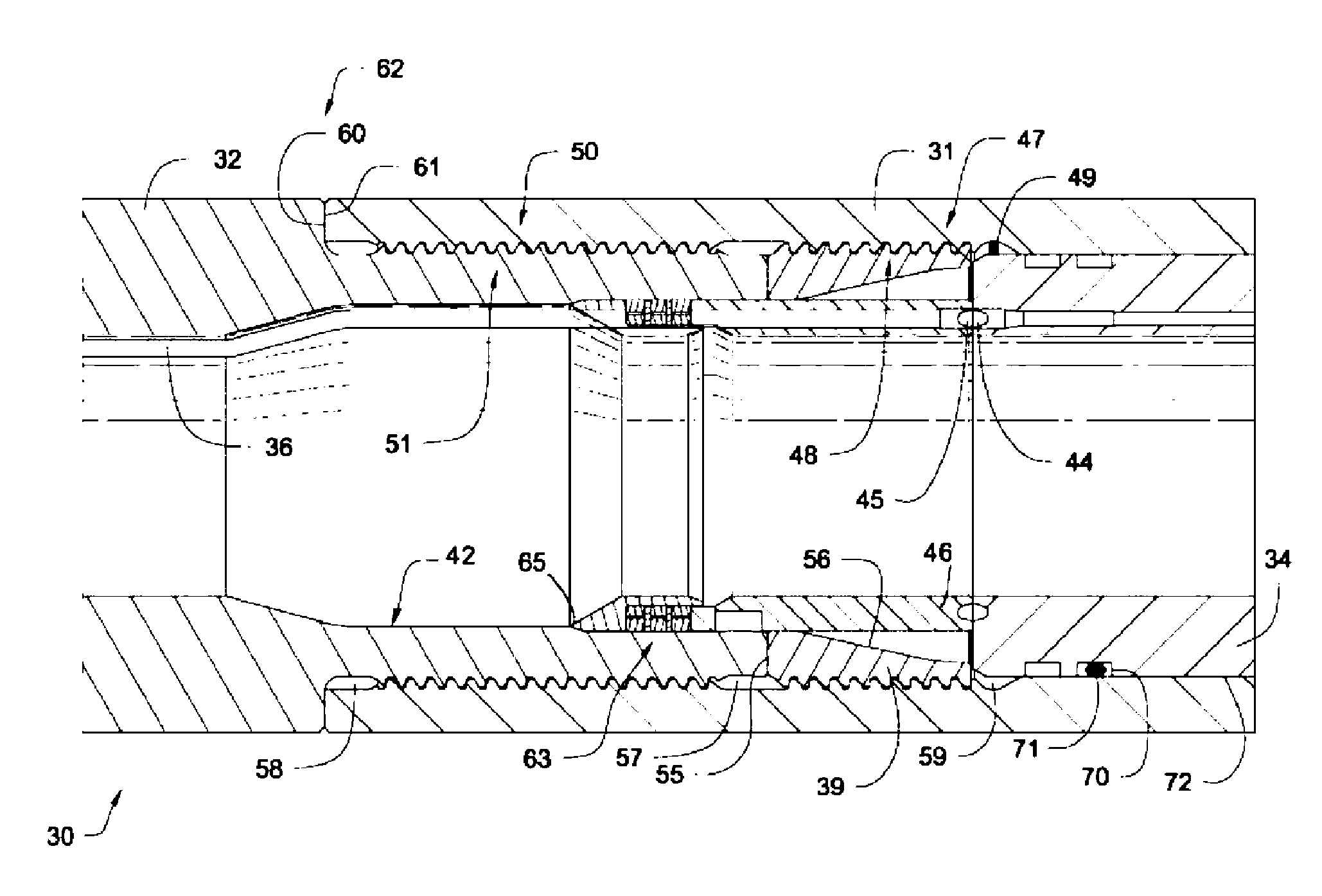
The patent describes a double shouldered downhole tool connection that includes a secondary shoulder component retained in the box connection between the primary shoulder components. The secondary shoulder component is designed to transfer a portion of the makeup load to the box connection. The downhole tool may include electronics modules, generators, gyroscopes, power sources, and stators, among others. The floating component may include electronic components such as signal filtering circuitry, signal error checking circuitry, device control circuitry, modems, digital processors, optical regulators, optical transmitters, optical receivers, repeater circuitry, sensors, routers, switches, memory, amplifiers, clock sources, data compression circuitry, data rate adjustment circuitry, piezoelectric devices, magnetostrictive devices, gauges, wireless transceivers, digital / optical converters, analog / optical converters, digital / analog converters, and microcontrollers. The floating component may be separated from the secondary shoulder component by at least 0.01 mm. The secondary shoulder component is connected to the pin connection through an O-ring and a biasing element. The communication elements may be selected from the group consisting of inductive couplers, direct electrical contacts, optic couplers, and combinations therof. The secondary shoulder has an interface with the box connection that may aid in the insertion of the secondary shoulder. The secondary shoulder has a tapered internal surface to distribute the makeup load. The pin and box connections may have stress relief grooves and thread roots comprising at least two tapers. The technical effects of this invention include reducing damage to downhole equipment caused by the stresses experienced by the downhole tool string, providing a floating component that is free of the normal loads experienced by the downhole tool string, and improving the transfer of makeup load to the box connection.

Problems solved by technology

Nevertheless, in downhole telemetry systems transmitting data on wires or cables integrated directly into the drill string, few if any useable implementations are known for repeating and amplifying data signals.
Furthermore, none of the references address all of the challenges, such as cable routing from the repeater up and down the drill string, that are inherent in wired solutions.

Method used


Image

  • Downhole Tool
  • Downhole Tool
  • Downhole Tool

Examples


Embodiment Construction

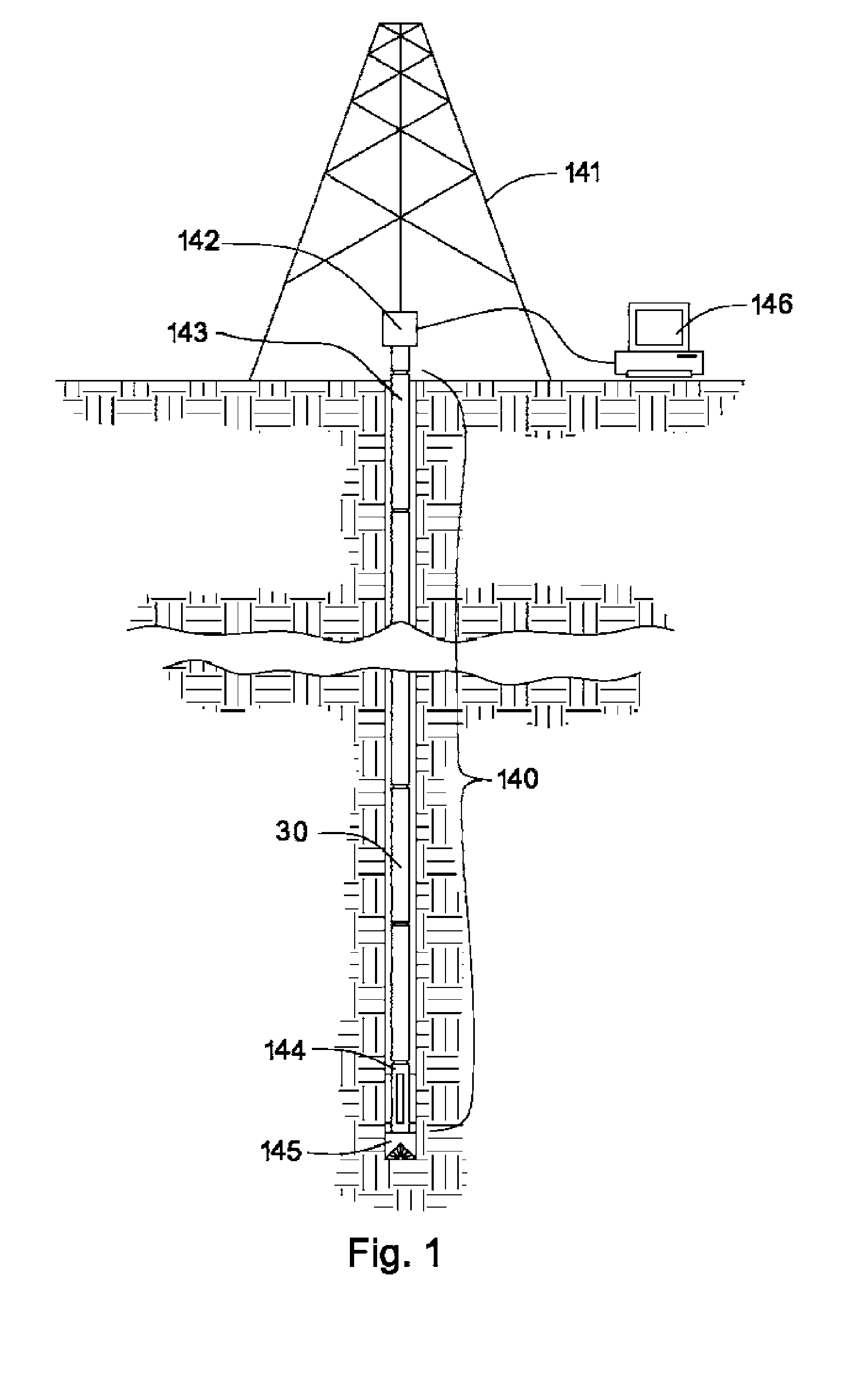
[0035]FIG. 1 shows a drill string 140 suspended by a derrick 141. A bottom-hole assembly 144 is located at the bottom of a bore hole 143 and comprises a drill bit 145. As the drill bit 145 rotates downhole the drill string 140 advance further into the earth. The bottom-hole assembly 144 and / or downhole tools 30, such as drill pipes, may comprises data acquisition devices (not shown) which may gather data. The data may be sent to the surface via a transmission system to a data swivel 142. The data swivel 142 may send the data to the surface equipment 146. Further, the surface equipment 146 may send data and / or power to downhole tools 30 and / or the bottom-hole assembly 144.

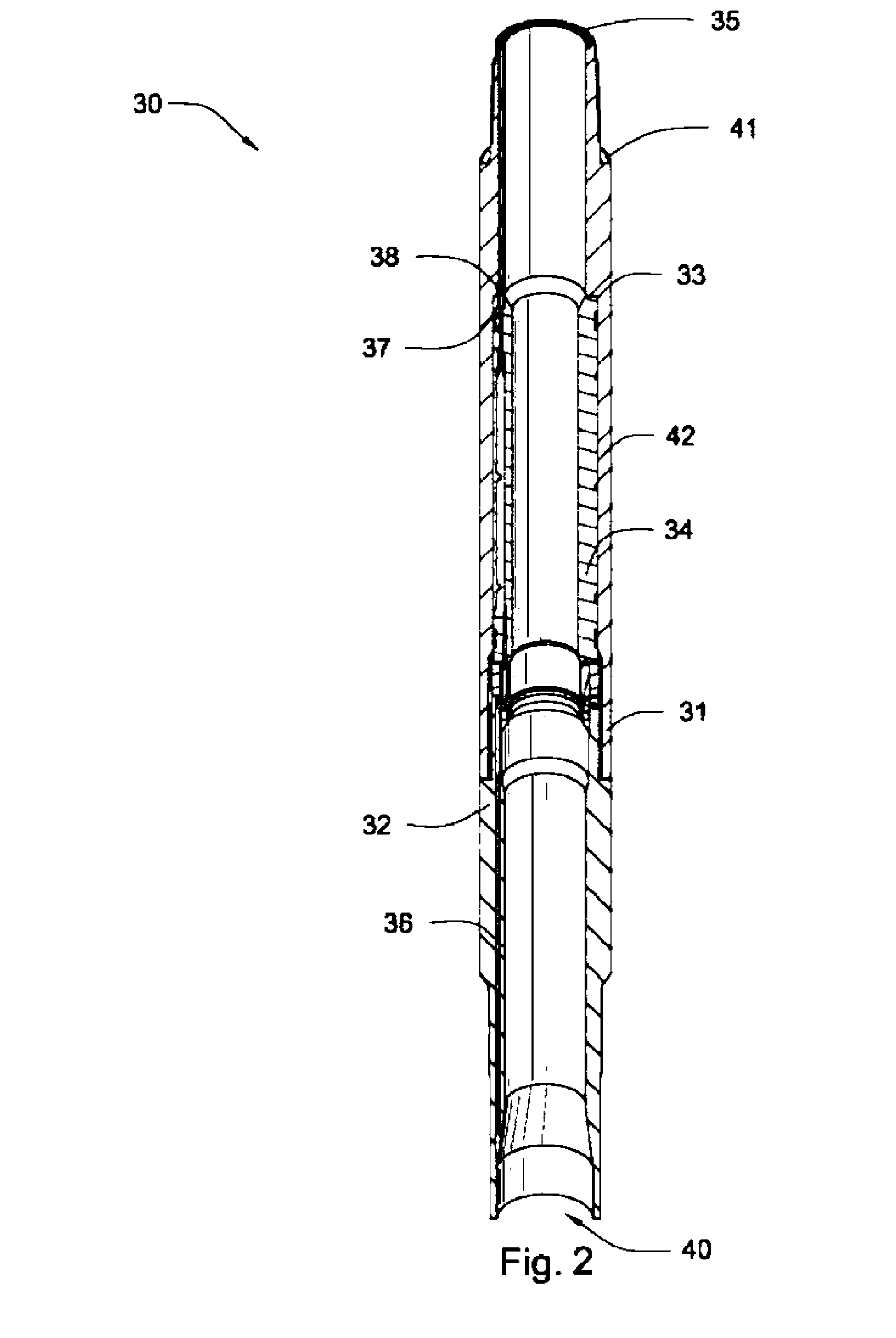
[0036]FIG. 2 is a cross sectional view of a downhole tool 30 comprising a box connection 31 and a pin connection 32. Box connection 31 and pin connection 32 are located in a mid-body section of the downhole tool 30. The downhole tool 30 also comprises a box end 40 and a pin end 35 which are located at the ends of t...


PUM


Abstract

A double shouldered downhole tool connection comprises box and pin connections having mating threads intermediate mating primary and secondary shoulders. The connection further comprises a secondary shoulder component retained in the box connection intermediate a floating component and the primary shoulders. The secondary shoulder component and the pin connection cooperate to transfer a portion of makeup load to the box connection. The downhole tool may be selected from the group consisting of drill pipe, drill collars, production pipe, and reamers. The floating component may be selected from the group consisting of electronics modules, generators, gyroscopes, power sources, and stators. The secondary shoulder component may comprises an interface to the box connection selected from the group consisting of radial grooves, axial grooves, tapered grooves, radial protrusions, axial protrusions, tapered protrusions, shoulders, and threads.

Description

CROSS REFERENCE TO RELATED APPLICATIONS [0001] The present application is a continuation-in-part of co-pending U.S. patent application Ser. No. 10 / 613,549 to Hall et, al. filed on Jul. 2, 2003, which is herein incorporated by reference for all that it discloses.FEDERAL SPONSORSHIP [0002] This invention was made with government support under Contract No. DE-FC26-01NT41229 awarded by the U.S. Department of Energy. The government has certain rights in the invention.BACKGROUND OF THE INVENTION [0003] This invention relates to oil and gas drilling, and more particularly to apparatus and methods for reliably transmitting information between downhole drilling components. [0004] The need for signal repeaters to counteract signal loss encountered when transmitting data from downhole components to the earth's surface is known or has been suggested. Nevertheless, in downhole telemetry systems transmitting data on wires or cables integrated directly into the drill string, few if any useable imp...

Claims


Application Information

Patent Timeline
Patent Type & Authority Applications(United States)
IPC IPC(8): E21B17/02E21B47/12G01V11/00
CPCE21B47/01G01V11/002E21B47/122E21B47/13
Inventor HALLMURADOV, ANDREIPIXTON, DAVID S.DAHLGREN, SCOTT STEVENBRISCOE, MICHAEL A.
Owner INTELLISERV
Learn More