Method and system for pilot light safety

a technology for pilot lights and safety devices, applied in the field of control systems, can solve the problems of inability to operate, system overflow, and inability to operate, and achieve the effect of reducing the number of pilot lights, and reducing the safety of pilot lights

Active Publication Date: 2005-07-28
ADEMCO INC
View PDF49 Cites 15 Cited by
  • Summary
  • Abstract
  • Description
  • Claims
  • Application Information

AI Technical Summary

Benefits of technology

[0009] According to the exemplary embodiments, a method of using a controller to prevent ignition of a pilot flame includes the steps of providing a gas valve. The gas valve includes a gas inlet in fluid communication with a first chamber, a second chamber in selective fluid communication with the first chamber, a gas outlet in selective fluid communication with the second chamber, a pilot light outlet in fluid communication with the second chamber,

Problems solved by technology

In this respect, appliances with external power sources may be difficult to use in certain situations due to availability and/or proximity of a suitable power source.
Additionally, such systems typically do not function in the event of a power outage, which is undesirable.
While a thermo-mechanical back-up control system may be included

Method used


Image

  • Method and system for pilot light safety
  • Method and system for pilot light safety
  • Method and system for pilot light safety

Examples


Embodiment Construction

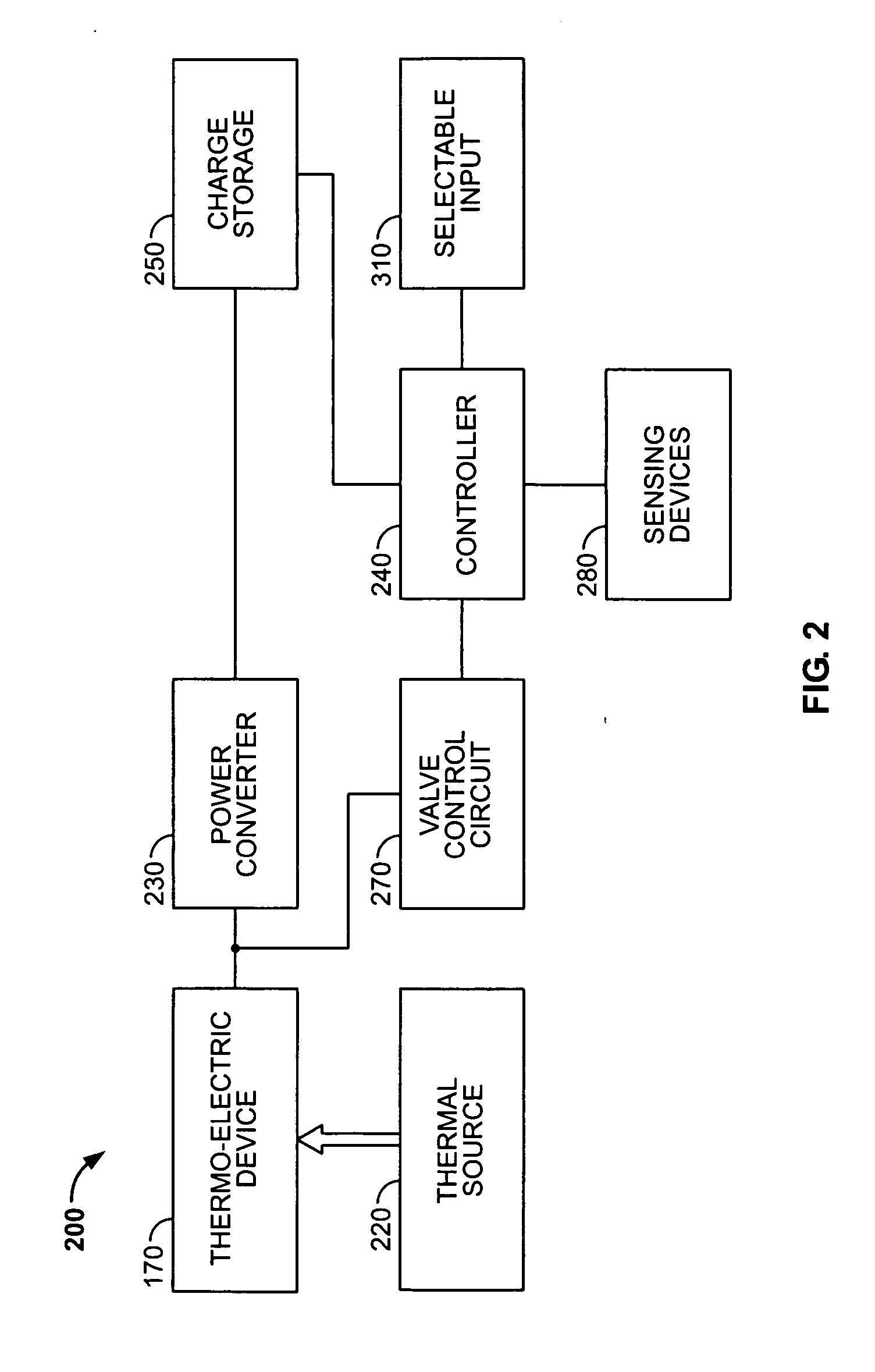
1. Exemplary Architecture

[0025] It should be appreciated that while exemplary embodiments are described with particular reference to an appliance control system for controlling a gas-fired water heating device, the present invention is contemplated for use with other appliances, including those which generate heat using electricity, a heat pump, oil, and the like. In addition, the gas-fired heating appliance may use a variety of suitable ignition systems, including standing pilot ignition, spark ignition, and hot surface ignition.

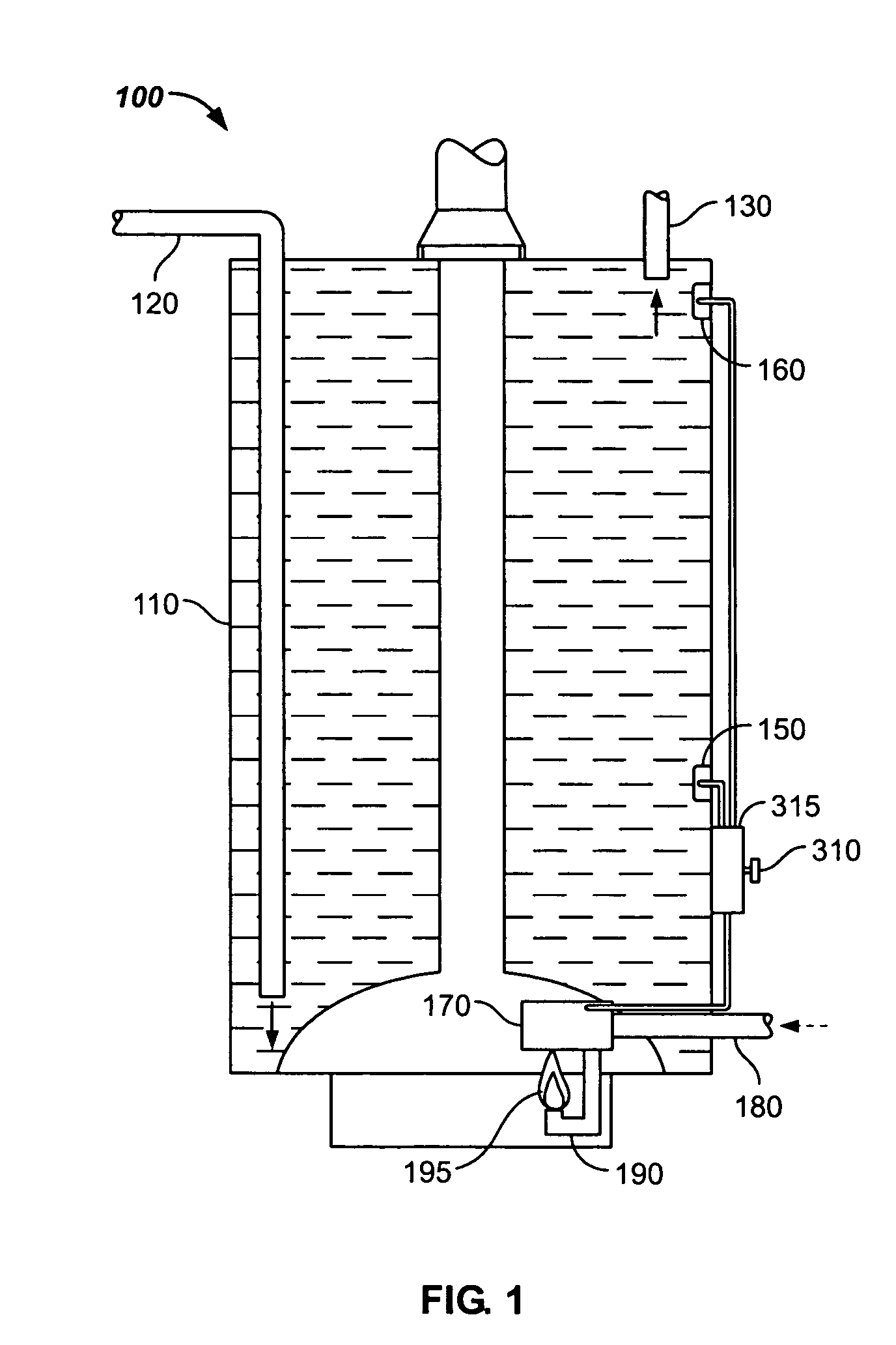
[0026] Referring now to the drawings, which illustrate exemplary embodiments only and are not for purposes of limiting the claims, FIG. 1 depicts an exemplary embodiment of a water heating device (“water heater”) 100. Water heater 100 might include a storage tank 110 for storing water that has been, or is to be heated. Water heater 100 might also include a water supply feed pipe (typically cold water) 120, and a hot water exit pipe 130. Additionally, wate...


PUM


Abstract

A gas valve includes a gas inlet in fluid communication with a first chamber, a second chamber in selective fluid communication with the first chamber, a gas outlet in selective fluid communication with the second chamber, a pilot light outlet in fluid communication with the second chamber, and a bypass channel in fluid communication with the second chamber and in fluid communication with the first chamber. The bypass channel limits bypass gas flow to an amount that is insufficient to ignite a pilot flame at the pilot light outlet when the second channel is in fluid communication with the gas outlet.

Description

CROSS-REFERENCE [0001] This application is a continuation-in-part of U.S. patent application Ser. No.: 10 / 766,107, filed 02 Apr. 2003, which is incorporated by reference herein.BACKGROUND [0002] 1. Field of the Invention [0003] The present invention relates generally to a controller, and more particularly relates to a control system for controlling an appliance, such as a gas-fired heating device. [0004] 2. Description of the Related Art [0005] Gas-powered appliances typically have some control system included for controlling the operation of the appliance. In this context, a gas-powered appliance may be a water heater, a fireplace insert, or a furnace, for example. Also in this context, “gas-powered” typically means that natural gas or liquid propane gas is used as a primary fuel source. Current control systems used in gas-powered appliances are typically powered by a source external to the appliance, or take the form of a thermo-mechanical system, of which both approaches have cer...

Claims


Application Information

Patent Timeline
IPC IPC(8): F23N1/00F23N5/00F23N5/14G05D7/06
CPCF23N1/002G05D7/0647F23N5/14F23N5/00Y10T137/1407B01D59/12
Inventor MUNSTERHUIS, SYBRANDUS B.V.
Owner ADEMCO INC
Why Eureka
Try Eureka