Brush and brush holder assembly for a micro horsepower motor

a micro-horsepower, brush technology, applied in the direction of current collectors, dynamo-electric machines, electrical apparatus, etc., can solve the problems of wear on commutators, and reducing the efficiency of electric motors, so as to achieve more stable and efficient effects

Inactive Publication Date: 2005-07-28
MOLON MOTOR COIL
View PDF23 Cites 7 Cited by
  • Summary
  • Abstract
  • Description
  • Claims
  • Application Information

AI Technical Summary

Benefits of technology

[0020] A primary object of the invention is to provide a brush and a brush holder system for carrying minimal current to a micro motor or the like so that the spring does not fail, arcing is eliminated and the commutator is not destroyed.
[0021] A secondary object of the invention is to provide a brush and a brush holder system that makes a micro motor, operating at 0.001 HP or less, more stable and more efficient than micro motors using known prior art brush and brush holder systems.
[0022] In the invention, an independent coil wire spring provides a constant pressure on the brush and the current is carried to the brush by a wavy pin tail or a shunt so that there is no spring retardation caused by current flow therein.

Problems solved by technology

As a result of the heat generated by the electric current passing through the leaf spring, arcing often occurs and causes wear on the commutator.
This wear consequently reduces the efficiency of the electric motor.
Without such failure being seen, the arcing becomes heavy, causes wear and reduces the efficiency of a related commutator (not shown).
However, it cannot carry a high current for a long period of time.
Also, the brush length is very short, thus reducing the operational HP.
Furthermore, the blade may some times lose tension and consequently the efficiency of the motor is reduced.

Method used


Image

  • Brush and brush holder assembly for a micro horsepower motor
  • Brush and brush holder assembly for a micro horsepower motor
  • Brush and brush holder assembly for a micro horsepower motor

Examples


Embodiment Construction

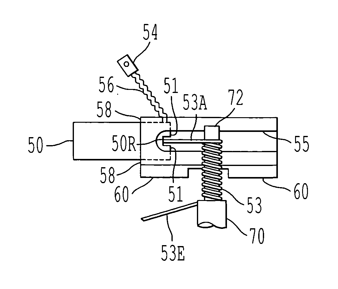
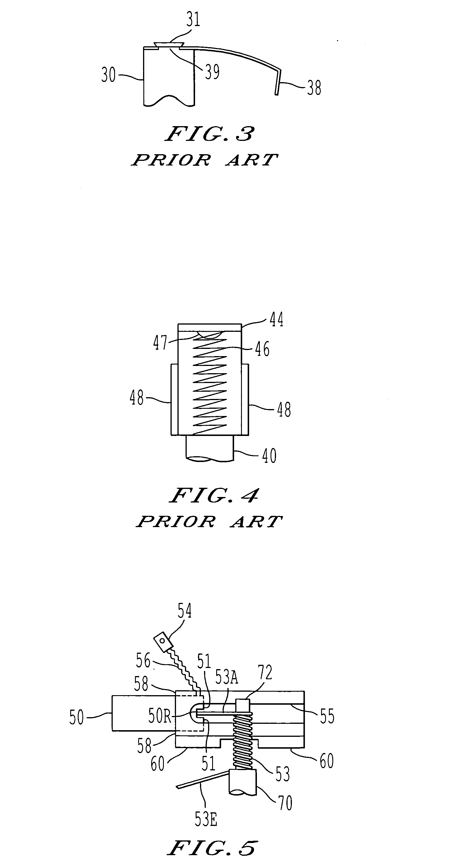
[0030] Referring now to the drawings, wherein like reference numerals designate identical or corresponding parts throughout the schematic view, attention is directed to FIG. 5 which shows the preferred embodiment of the invention.

[0031] The features of the invention will become apparent in the course of the following description of the exemplary embodiment which is given for illustration of the invention and is not intended to limit the invention to the specific embodiment shown in FIG. 5.

[0032] In FIG. 5, a connection 54 carries electric current to a wavy pin tail or shunt 56 that contacts a tip 51 of a carbon brush 50. The electric current may be either AC or DC. However, DC is preferred. The brush 50 is surrounded partly at one end where the tip 51 is located by a brass brush holder 58 which has a longitudinal cutout portion 55. The brush holder 58 is attached to a part of a plastic end bell 60.

[0033] An independent coil wire spring 53 is wrapped tightly around a projection 72...


PUM


Abstract

A brush and brush holder assembly for a micro horsepower electric motor includes a brush having a tip with a recessed portion; a brush holder surrounding the tip of the brush and having a cutout portion; a shunt carrying current to the tip of the brush; and an independent coil wire spring which does not carry current. This independent coil wire spring has an end which protrudes into the cutout portion of the brush holder and applies constant pressure to the recessed portion in the tip of the brush. The brush and brush holder assembly also has an electrical connection attached to the shunt. This electrical connection may carry direct current to the shunt.

Description

BACKGROUND OF THE INVENTION [0001] 1. Field of the Invention [0002] The invention relates to a brush and a holder assembly therefor, particularly for a micro horsepower (hereinafter HP) electric motor. [0003] 2. Discussion of the Prior Art [0004] A micro HP electric motor may be defined as one operating at 0.001 HP or less. Such a micro HP electric motor may have a maximum torque between 1.2 and 1.6 inch-ounces. Similarly, a fractional HP electric motor may be defined as an electric motor operating at less than one HP but more than 0.001 HP. [0005] In the known prior art, a leaf spring usually acts as a brush holder. This leaf spring routinely gets hot because current is carried through the leaf spring to the brush itself. As a result of the heat generated by the electric current passing through the leaf spring, arcing often occurs and causes wear on the commutator. This wear consequently reduces the efficiency of the electric motor. [0006] A preliminary patentability search uncover...

Claims


Application Information

Patent Timeline
Patent Type & Authority Applications(United States)
IPC IPC(8): H01R39/38
CPCH01R39/383H01R39/381
Inventor TSERGAS, ATHANASE N.
Owner MOLON MOTOR COIL
Why Eureka
Try Eureka