Variable ratio transmission elements for motor drive shafts

a transmission element and variable ratio technology, applied in mechanical actuated clutches, generators/motors, gears, etc., can solve problems such as contact radius changes, and achieve the effect of increasing the circumference of the transmission element and increasing the radius

Active Publication Date: 2005-07-28
THE JOHN HOPKINS UNIV SCHOOL OF MEDICINE
View PDF9 Cites 30 Cited by
  • Summary
  • Abstract
  • Description
  • Claims
  • Application Information

AI Technical Summary

Benefits of technology

[0015] According to another set of embodiments, a transmission element includes an axle, multiple spokes connected to the axle, and multiple rolled electroactive polymer (EAP) devices. Each rolled EAP device has at least a first pair of input electrodes. The EAP devices are arranged azimuthally around the axle at a particular radius and are mechanically connected to the spoke

Problems solved by technology

Deformation of the rolled EAP device

Method used


Image

  • Variable ratio transmission elements for motor drive shafts
  • Variable ratio transmission elements for motor drive shafts
  • Variable ratio transmission elements for motor drive shafts

Examples


Embodiment Construction

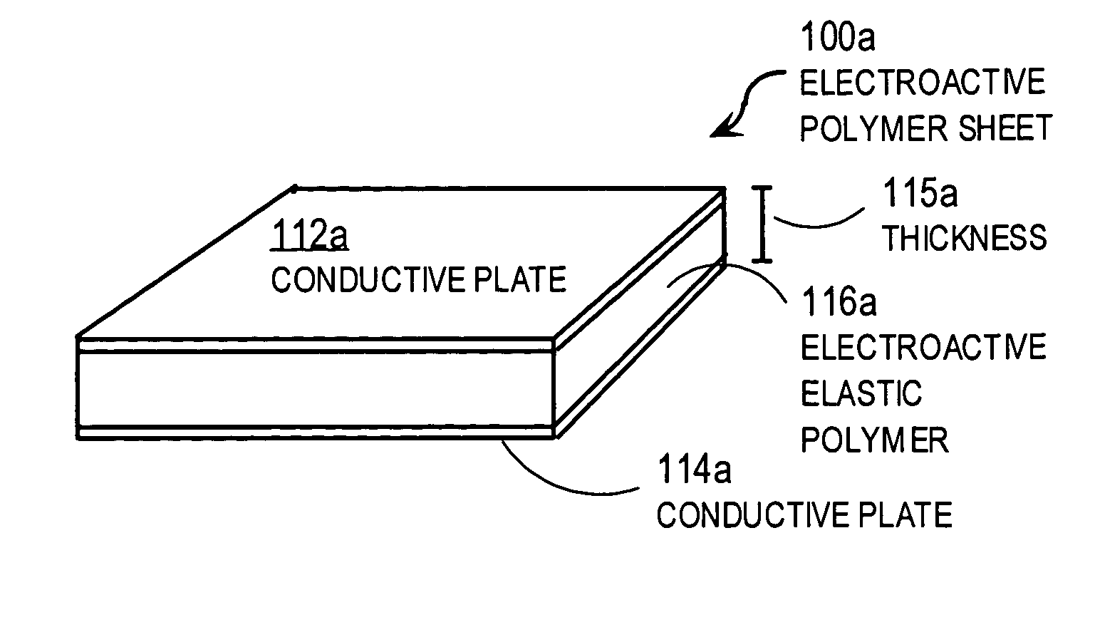
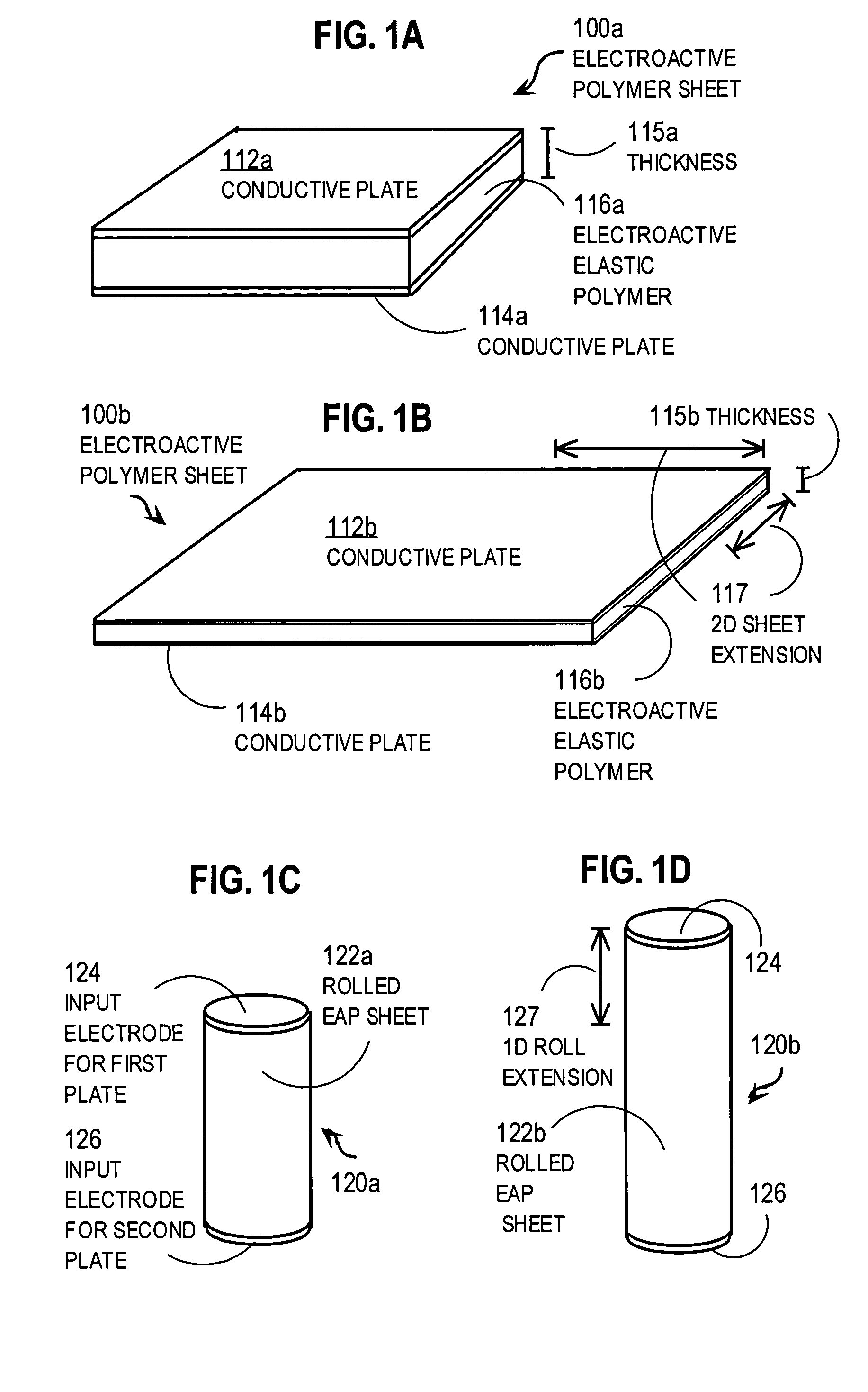
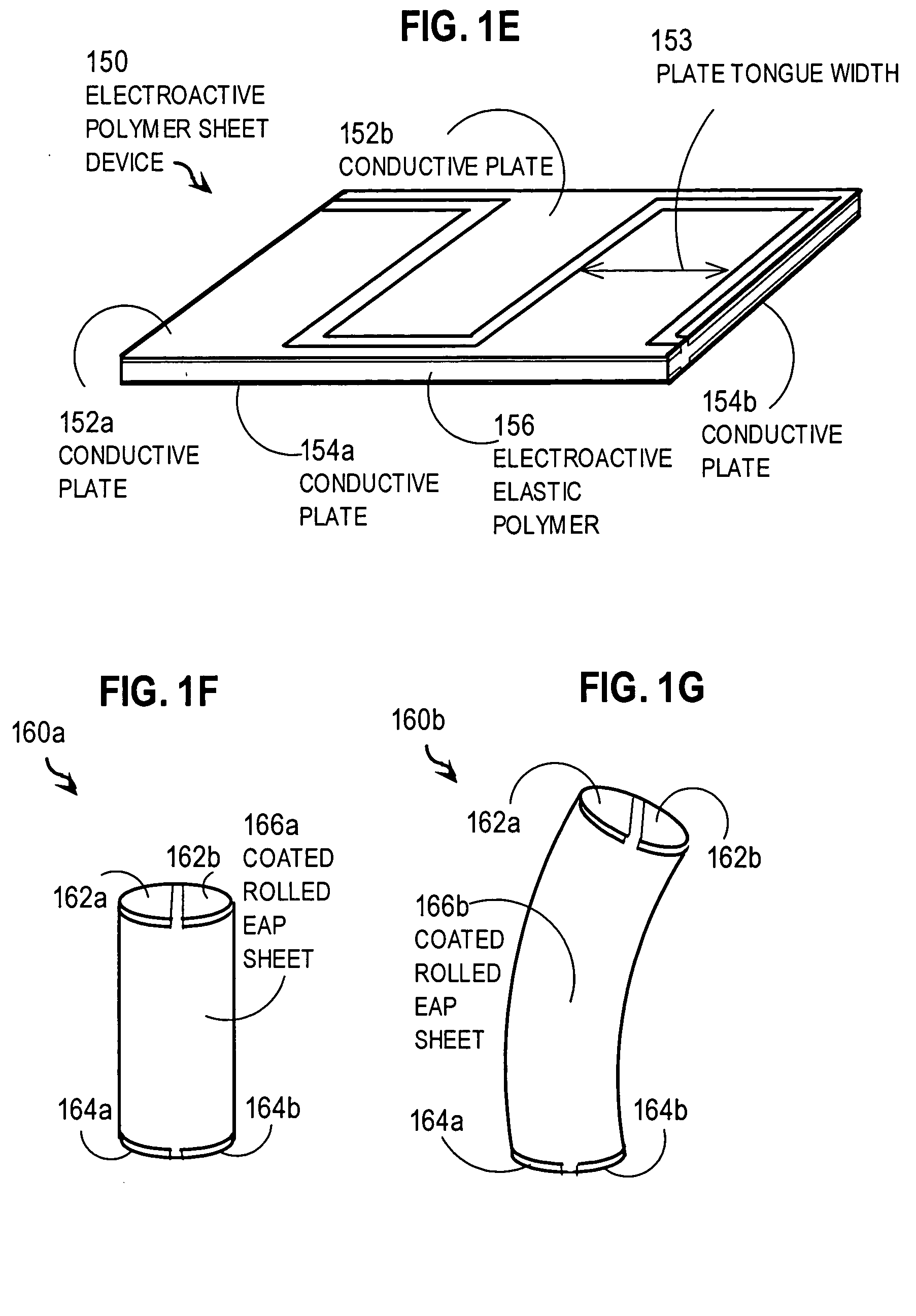
[0040] Motor transmissions are described that change their circumferences, such as by using electroactive polymer (EAP) devices. In the following description, for the purposes of explanation, numerous specific details are set forth in order to provide a thorough understanding of the present invention. It will be apparent, however, to one skilled in the art that the present invention may be practiced without these specific details. In other instances, well-known structures and devices are shown in block diagram form in order to avoid unnecessarily obscuring the present invention.

[0041] Many embodiments of the invention are described in the context of a transmission for a lightweight vehicle of low radar reflectivity, which is made possible using many of the described embodiments. For example, in some embodiments, the transmission element is used with a lightweight, low-metallic motor using rolled EAP devices with sufficient horsepower, as described in Krill. However, the invention i...


PUM


Abstract

A motor transmission element includes an axle, an expandable circumferential component and multiple rolled electroactive polymer (EAP) devices. The circumferential component is located at a contact radius from the axle for connection to a different rotating body and is mechanically connected to the axle. The rolled EAP devices are mechanically connected to the circumferential component and the axle. Each rolled EAP device has a pair of input electrodes and is configured to deform substantively parallel to a roll longitudinal axis upon application of a voltage difference. Deformation of a rolled EAP device causes a change in the contact radius. A voltage difference that expands the rolled EAP device increases the contact radius, and thereby the circumference of the transmission element. By varying the voltage, a continuously variable ratio can be achieved between a rate of rotation of the transmission element and a rate of rotation of the second body.

Description

CROSS-REFERENCE TO RELATED APPLICATIONS [0001] This application claims benefit of U.S. Provisional Application 60 / 539,680, filed Jan. 28, 2004, the entire contents of which are hereby incorporated by reference as if fully set forth herein, under 35 U.S.C. § 119(e). [0002] This application is related to U.S. non-provisional patent application Ser. No. ______ (Attorney Docket No. 2034-SPL) filed on even date herewith by inventor Jerry A. Krill, entitled “Dielectric Motors with Electrically Conducting Rotating Drive Shafts and Vehicles Using Same” (referenced hereinafter as Krill), which is incorporated herein by reference in its entirety.BACKGROUND OF THE INVENTION [0003] 1. Field of the Invention [0004] The present invention relates to transmissions for motor drive shafts; and in particular to variable ratio transmission elements for rotating drive shafts, including transmission elements that use electroactive polymer devices. [0005] 2. Description of the Related Art [0006] Conventio...

Claims


Application Information

Patent Timeline
IPC IPC(8): H01L21/00
CPCF16D13/12Y10S310/80F16H15/04F16D28/00
Inventor KRILL, JERRY A.
Owner THE JOHN HOPKINS UNIV SCHOOL OF MEDICINE
Why Eureka
Try Eureka