Voltage regulator

a voltage regulator and voltage regulator technology, applied in the direction of electric variable regulation, process and machine control, instruments, etc., can solve the problems of increased consumption current, deterioration of responsibility, and deterioration of stability, so as to achieve high speed responsibility, low power consumption, and stable operation

Active Publication Date: 2005-07-28
ABLIC INC
View PDF8 Cites 23 Cited by
  • Summary
  • Abstract
  • Description
  • Claims
  • Application Information

AI Technical Summary

Benefits of technology

[0015] Though the voltage regulator of the present invention described above has a three-stage amplification circuit configuration, the phase compensation for the differential amplifier is carried out by the parallel-connected resistor and capacitor, whereby the high speed responsibility can be realized for the voltage regulator with low power consumption, and the voltage regulator can stably operate even with a low output capacity.

Problems solved by technology

Accordingly, there is a problem in that the responsibility is deteriorated.
In addition, when the responsibility is improved, the consumption current is increased or the stability is deteriorated, so that a large capacitance is required for the output of the voltage regulator.

Method used


Image

  • Voltage regulator
  • Voltage regulator
  • Voltage regulator

Examples


first embodiment

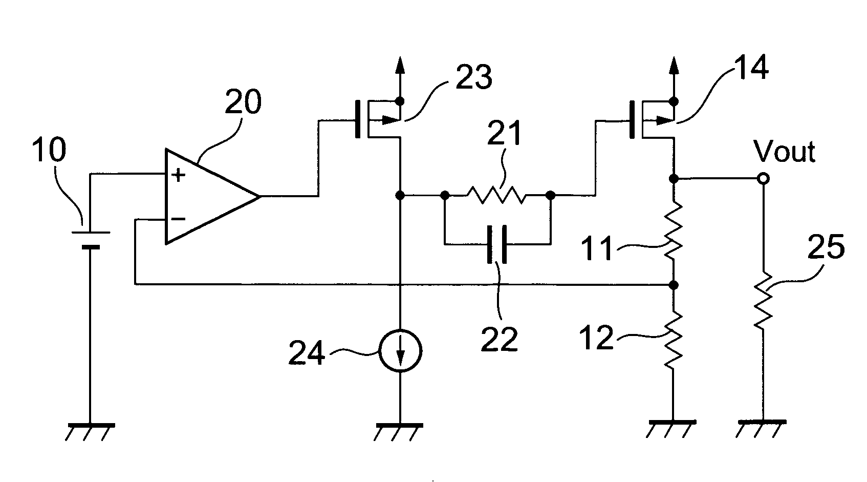
[0022]FIG. 1 is a circuit diagram of a voltage regulator according to a first embodiment of the present invention. The voltage regulator of the first embodiment includes a reference voltage circuit 10, bleeder resistors 11 and 12, a differential amplifier 20, a MOS transistor 23, parallel-connected resistor 21 and capacitor 22, an output transistor 14, and a load resistor 25.

[0023] Since the differential amplifier 20 is a voltage one-stage amplification circuit, and its output is amplified by the MOS transistor 23 constituting a common source amplification circuit, and by a common source circuit including the output transistor 14 and the load transistor 25, a three-stage amplification circuit is provided in terms of the voltage regulator. With the three-stage amplification, a GB product can be made large even with a low consumption current, and hence the responsibility of the voltage regulator can be enhanced. However, the voltage is easy to lag by 180° or more in the three-phase v...

second embodiment

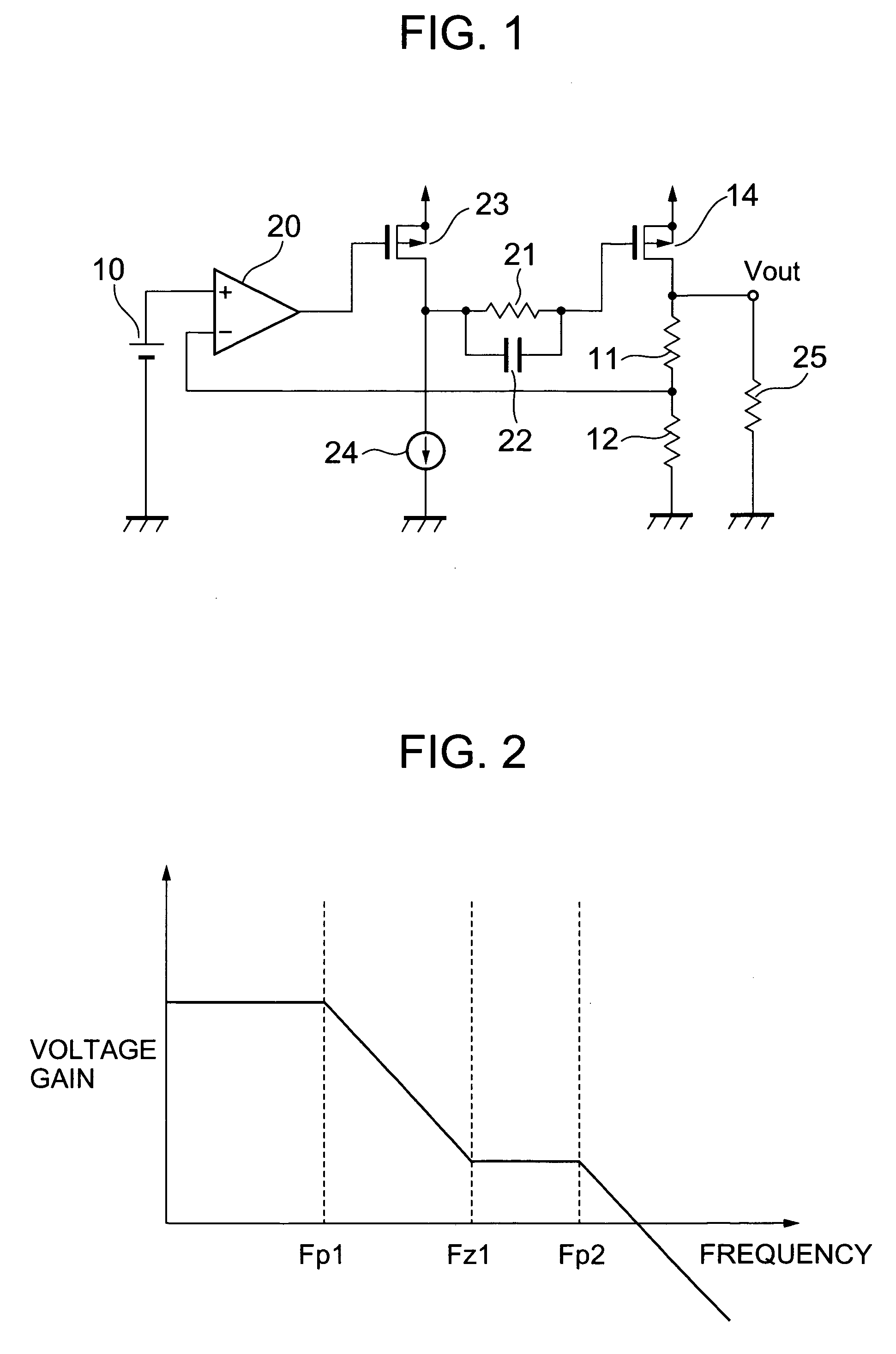
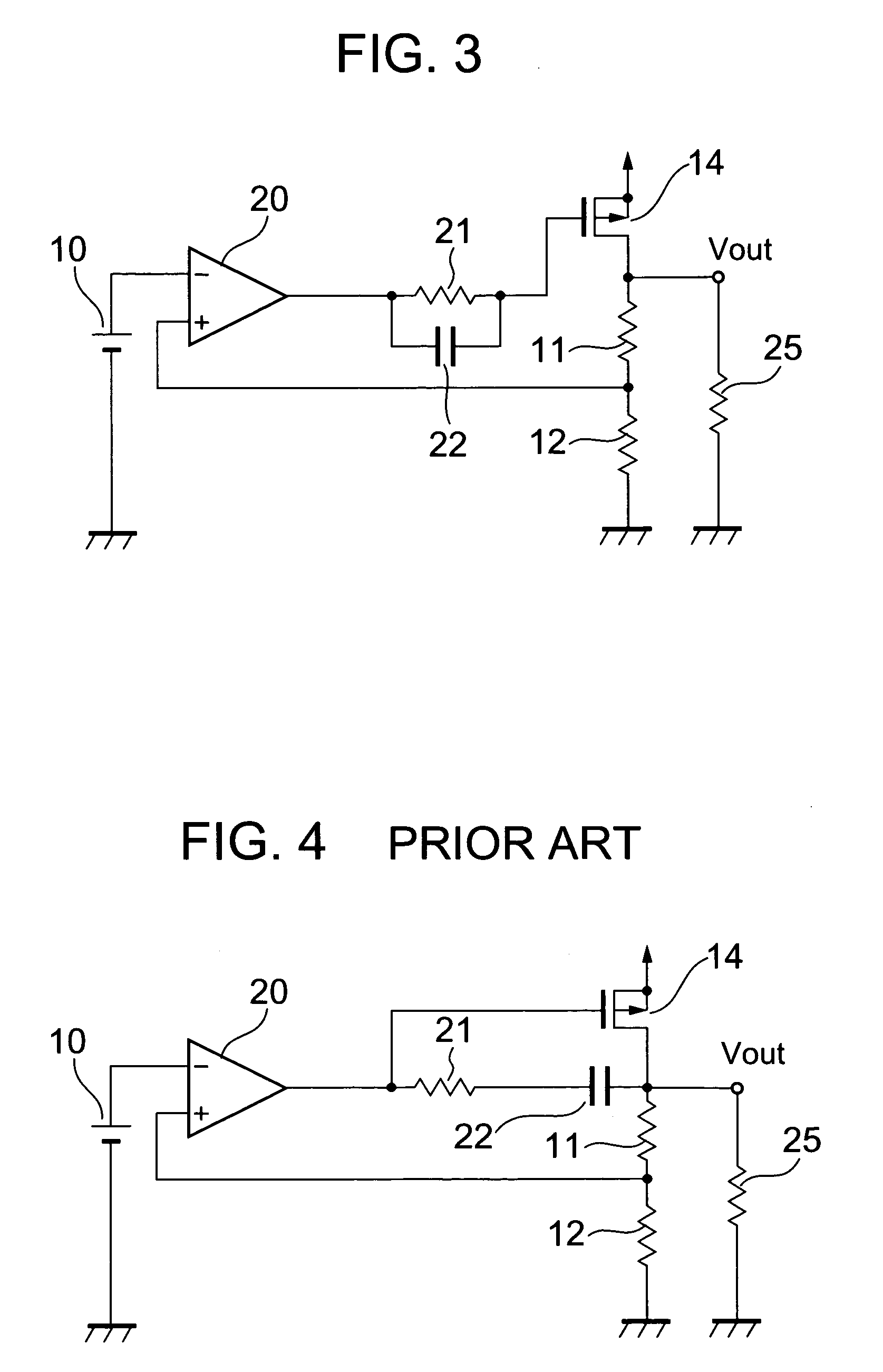
[0030]FIG. 3 is a circuit diagram of a voltage regulator according to a second embodiment of the present invention. A reference voltage circuit 10, bleeder resistors 11, and 12, an output transistor 14, and a load resistor 25 are the same as those in the conventional voltage regulator shown in FIG. 4. A point of difference from the first embodiment is that there is no voltage amplification circuit in a second stage. Even in the case of the voltage regulator as shown in FIG. 3, insertion of a resistor for phase compensation makes it possible to obtain the same effects as those in the first embodiment. In the case of the conventional phase compensation having the two-stage voltage amplification, it is necessary to newly insert a resistor and a capacitor between the gate and the source of the output transistor. However, as in the second embodiment shown in FIG. 3, the resistor is inserted in series with the gate of the output transistor, whereby the phase compensation can be carried ou...


PUM


Abstract

The present invention provides a voltage regulator which has high-speed responsibility with a low consumption current, and which can stably operate with a low output capacity. The voltage regulator includes: a reference voltage circuit, a voltage division circuit, a differential amplifier, an output transistor, a MOS transistor which has a gate to which an output of the differential amplifier is connected, a constant current circuit connected between a drain of the MOS transistor and the ground, and parallel-connected resistor and capacitor for phase compensation are connected between the drain of the MOS transistor and a gate of the output transistor.

Description

BACKGROUND OF THE INVENTION [0001] 1. Field of the Invention [0002] The present invention relates in general to a voltage regulator, and more particularly to an improvement in responsibility of the voltage regulator and a stable operation of the voltage regulator. [0003] 2. Description of the Related Art [0004]FIG. 4 is a circuit diagram of a conventional voltage regulator. [0005] The voltage regulator includes a reference voltage circuit 10 for generating a reference voltage, bleeder resistors 11 and 12 with which an output voltage Vout of the voltage regulator is divided, a differential amplifier 20 for amplifying a difference between the reference voltage and a voltage appearing at a node between the bleeder resistors 11 and 12, and an output transistor 14 which is controlled in accordance with an output voltage of the differential amplifier 20. [0006] When the output (reference) voltage of the reference voltage circuit 10 is assigned Vref, the voltage at the node between the ble...

Claims


Application Information

Patent Timeline
Patent Type & Authority Applications(United States)
IPC IPC(8): G05F1/56G05F1/40G05F1/575
CPCG05F1/575G05F1/56
Inventor KANAKUBO, YOSHIHIDE
Owner ABLIC INC
Why Eureka
Try Eureka