Inductive proximity sensor, particularly for sensing presence of ferrous and non-ferrous materials

Inactive Publication Date: 2005-07-28
M D MICRO DETECTORS
View PDF8 Cites 18 Cited by
  • Summary
  • Abstract
  • Description
  • Claims
  • Application Information

AI Technical Summary

Benefits of technology

[0014] The aim of the present invention is to eliminate the drawbacks cited above, by providing a sensor and a

Problems solved by technology

One of the greatest limitations of this type of known sensor is due to the fact that the switching distance depends on the type of material to be detected; while ferrous materials (here also referenced equally as ferromagnetic materials) are detected in an optimum manner, for non-ferrous or non-ferromagnetic materials, such as copper, the sensing characteristic can be degraded up to 25% of the activation distance of ferromagnetic materials.
I

Method used


Image

  • Inductive proximity sensor, particularly for sensing presence of ferrous and non-ferrous materials
  • Inductive proximity sensor, particularly for sensing presence of ferrous and non-ferrous materials
  • Inductive proximity sensor, particularly for sensing presence of ferrous and non-ferrous materials

Examples


Embodiment Construction

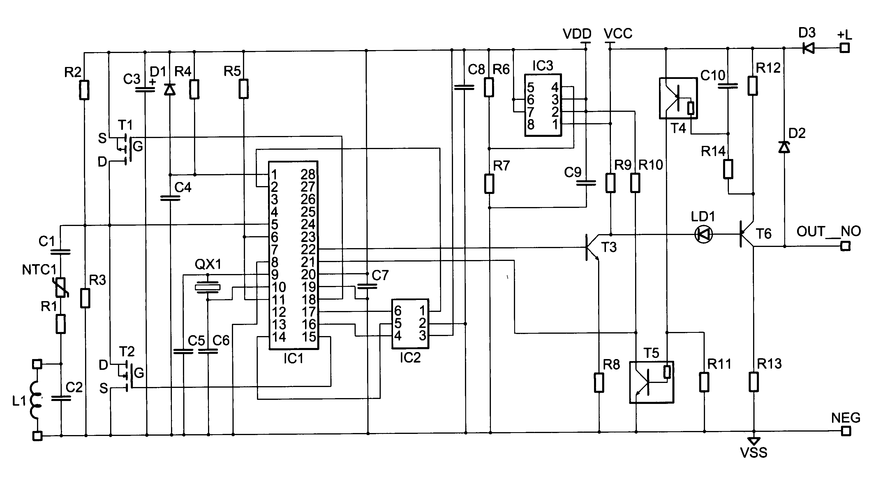
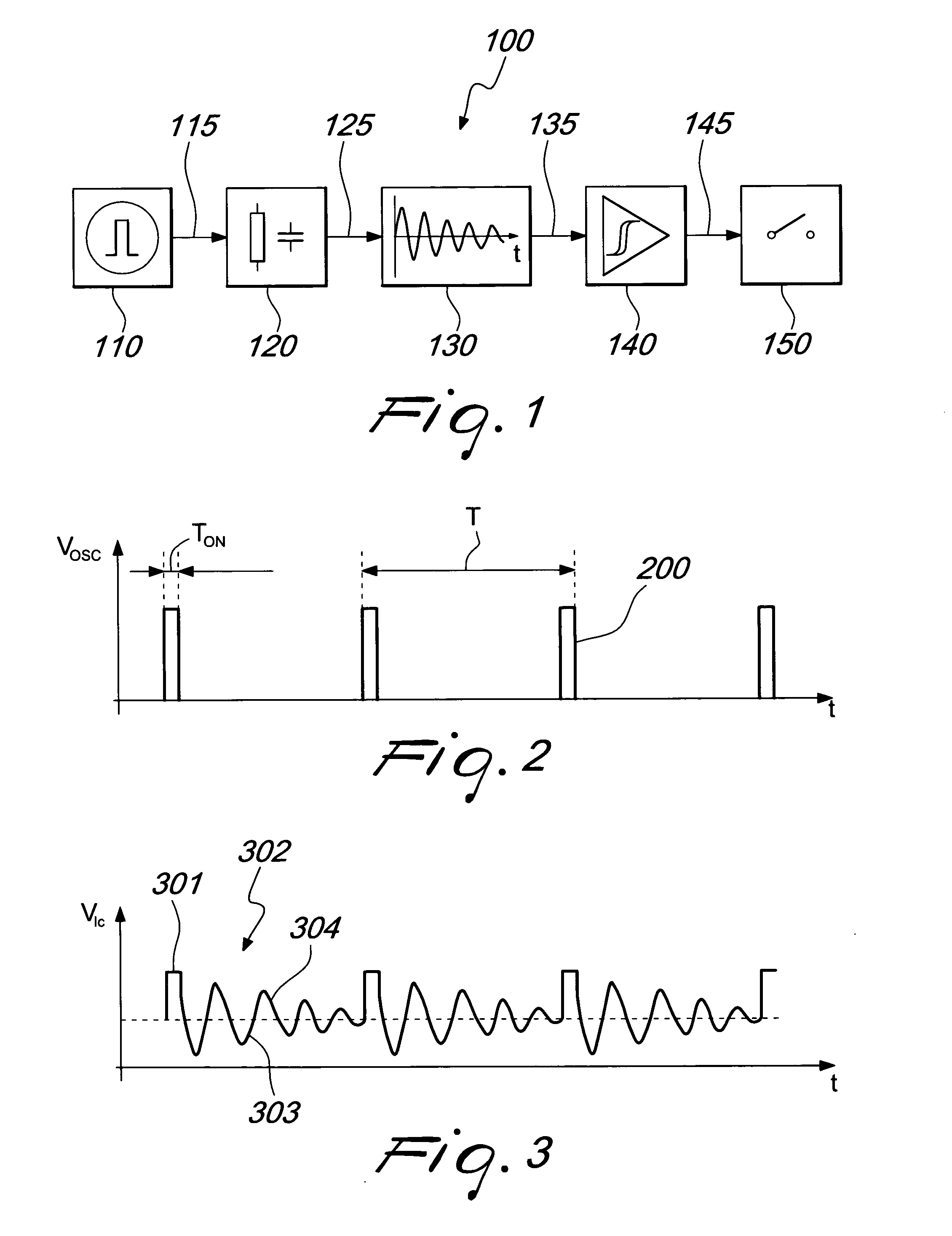
[0028] With reference to FIG. 1, a sensor according to the invention is generally designated by the reference numeral 100 and comprises a pulse generator 110, which is connected to the input of a resonant circuit 120. The pulse generator, according to a preferred embodiment, comprises a quartz oscillator, by means of which it is possible to generate periodically a voltage pulse. As an alternative, the pulse generator can comprise a ceramic resonator or an appropriately stable R-C circuit.

[0029] The resonant circuit is preferably of the parallel L-C type, i.e., it comprises an inductor and a capacitor connected in parallel. In alternative embodiments, the resonant circuit can be of the series L-C type or a tuned amplifier or more generally a circuit that comprises at least one inductor and a resonance frequency.

[0030] The output of the resonant circuit is connected to control means 130, which are preferably constituted by an analog-digital device that is capable of storing informat...


PUM


Abstract

An inductive proximity sensor, comprising a resonant circuit adapted to be affected electrically by the approach of metallic materials and comprising a control for storing a value of a sampling instant when an output value of the resonant circuit is measured, the sampling instant corresponding substantially to an instant in which a first amplitude of the response of the resonant circuit to a pulse applied thereto, measured in the presence of a ferromagnetic material arranged at a distance from the sensor, is substantially equal to a second amplitude of the pulse response measured in the presence of a non-ferromagnetic material arranged at the same distance.

Description

[0001] The present invention relates to an inductive proximity sensor, particularly for sensing presence of ferrous and non-ferrous materials. BACKGROUND OF THE INVENTION [0002] Inductive proximity sensors are known in the field of electric detectors. They are capable of detecting the presence of ferrous or non-ferrous metallic objects by utilizing the changes induced by said objects in the variable magnetic field generated by the sensor. [0003] The sensing element is usually constituted by a resonant circuit of the L-C type, which is composed of a capacitor and an inductor, typically connected to each other in parallel. The inductor is built so as to vary its characteristic parameters, such as inductance and loss resistance, when a metallic element is in its vicinity. [0004] In particular, it is known that the losses of a resonant circuit can be represented in electronic terms by an imaginary loss resistance, which summarizes the effects of the various losses of the circuit, such a...

Claims


Application Information

Patent Timeline
IPC IPC(8): G01V3/10
CPCG01V3/101
Inventor DEL MONTE, MAURO
Owner M D MICRO DETECTORS
Why Eureka
Try Eureka