Image rendering with multi-level Z-buffers

Inactive Publication Date: 2005-07-28
ELECTRONICS ARTS INC
View PDF11 Cites 24 Cited by
  • Summary
  • Abstract
  • Description
  • Claims
  • Application Information

AI Technical Summary

Benefits of technology

[0026] In one aspect of the present invention, the rendering can be performed on a stream of polygons received in an arbitrary order so that presorting the polygons is not required. Complex data structur

Problems solved by technology

Ray tracing generates realistic images but requires considerable processing.
While ray tracing is useful, it is not practical in many applications, such as those that require real-time rendering.
It cannot be processed properly if all that is available is a frame buffer and a Z-buffer, because there is not enough information about what is in front of that later polygon and how the current frame buffer values were determined.
One could search over all received polygons to seek out the overlapping polygons, but this is a computationally expensive operation and cannot usually be done in the limited time allotted to rendering in real-time.
This is acceptable in some images, but results in aliased edges and significant anomalies where many polygons are not fully opaque.
While this might work in theory, in practice this is difficult to do, because sorting takes considerable computing time, especially for a typical model of 10,000 polygons or more, and cannot deal with the problem o

Method used


Image

  • Image rendering with multi-level Z-buffers
  • Image rendering with multi-level Z-buffers
  • Image rendering with multi-level Z-buffers

Examples


Embodiment Construction

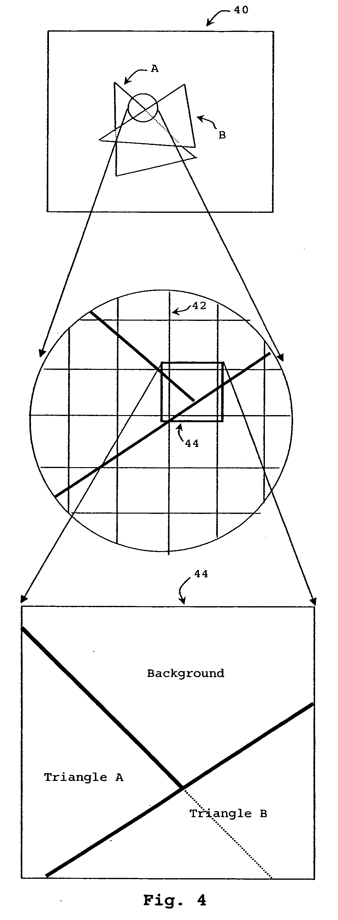
[0044] As shown in FIG. 4, when rendering elements (such as polygons), a pixel might cover more than one of those elements. In FIG. 4, a view plane 40 is what is being rendered and includes views of triangles A and B. In this case, when mapped to a pixel grid 42, one intersection of the two triangles is within the grid opening for a pixel 44. As illustrated by the zoomed-in view, pixel 44 is partially covered by triangle A, partially covered by triangle B, and partially covered by neither, so the background shows through. For ideal rendering of a color value for pixel 44, the contributions of each of those three elements should be included. This can be done by considering the relative areas of the pixel grid opening that each element occupies and the color / transparency values of each. If all of the polygons are sorted (either for the entire image or using scan strip approaches), then each element that overlaps each pixel can be considered, however for most practical processing syste...


PUM


Abstract

In an image processor, images are rendered into a plurality of frame buffers and corresponding Z-buffers by depth and the plurality of frame buffers are later combined to form the rendered image. The rendering can be implemented in hardware, software or a combination, for real-time or near real-time rendering of images. The plurality of frame buffers can be processed in parallel using a plurality of frame processors. The rendering can be performed on a stream of polygons received in an arbitrary order so that presorting the polygons is not required. Complex data structures and processing are not required, allowing a rendering process to proceed quickly, which is needed where the rendering must be done in real-time or near real-time for full- or nearly full-motion video. The image processor is provided with an indication of the number of frame buffers in the plurality of frame buffers. With this indication, the image processor can make the program memory allocations if needed and will process the image data with the required fidelity. The number of frame buffers used might vary as needed for different fidelities and images.

Description

CROSS-REFERENCE TO RELATED APPLICATIONS [0001] This application claims priority from co-pending U.S. provisional patent application No. 60 / 538,997 filed Jan. 22, 2004 entitled “Image Rendering with Multi-Level Z-Buffers”, which is hereby incorporated by reference, as if set forth in full in this document, for all purposes.FIELD OF THE INVENTION [0002] The present invention relates generally to image rendering and in particular to efficiently rendering an image from a geometric model of a plurality of objects using buffering. BACKGROUND OF THE INVENTION [0003] Computer generated images are often created by examining a geometric model of a view space and modeled objects in the view space. The geometric model of the objects can have arbitrary resolution, but typically each object is represented by a finite number of polygons, such as triangles, positioned in the view space and having a color, color pattern or texture over their surface, and an alpha value or values representing transpa...

Claims


Application Information

Patent Timeline
IPC IPC(8): G06T11/40G06T15/40
CPCG06T11/40G09G2340/10G06T15/405
Inventor HASHIMOTO, KAZUYUKILITZ, JEFFREY A.
Owner ELECTRONICS ARTS INC
Why Eureka
Try Eureka