Liquid crystal display

a technology of liquid crystal display and fluorescent tubes, which is applied in the field of liquid crystal display, can solve the problems of cfl being damaged or broken, cfl being vulnerable to bending, etc., and achieve the effect of improving the failure strength and shock resistance of cold cathode fluorescent tubes

Inactive Publication Date: 2005-07-28
HITACHI DISPLAYS
View PDF5 Cites 25 Cited by
  • Summary
  • Abstract
  • Description
  • Claims
  • Application Information

AI Technical Summary

Benefits of technology

[0018] In the liquid crystal display of the present invention, the failure strength of the c

Problems solved by technology

Especially, the CFL is vulnerable to bending.
Therefore, when an impact is applied under some conditions (e.g., product impact test) there

Method used


Image

  • Liquid crystal display
  • Liquid crystal display
  • Liquid crystal display

Examples


embodiment 1

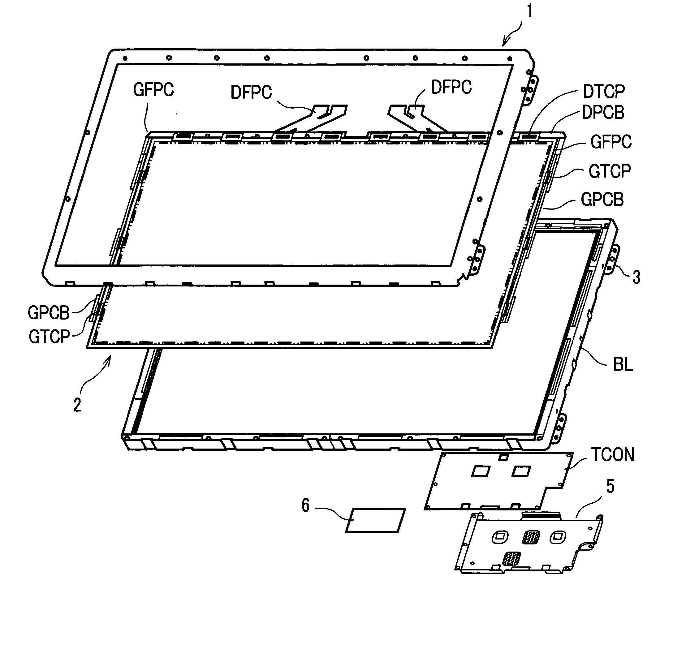
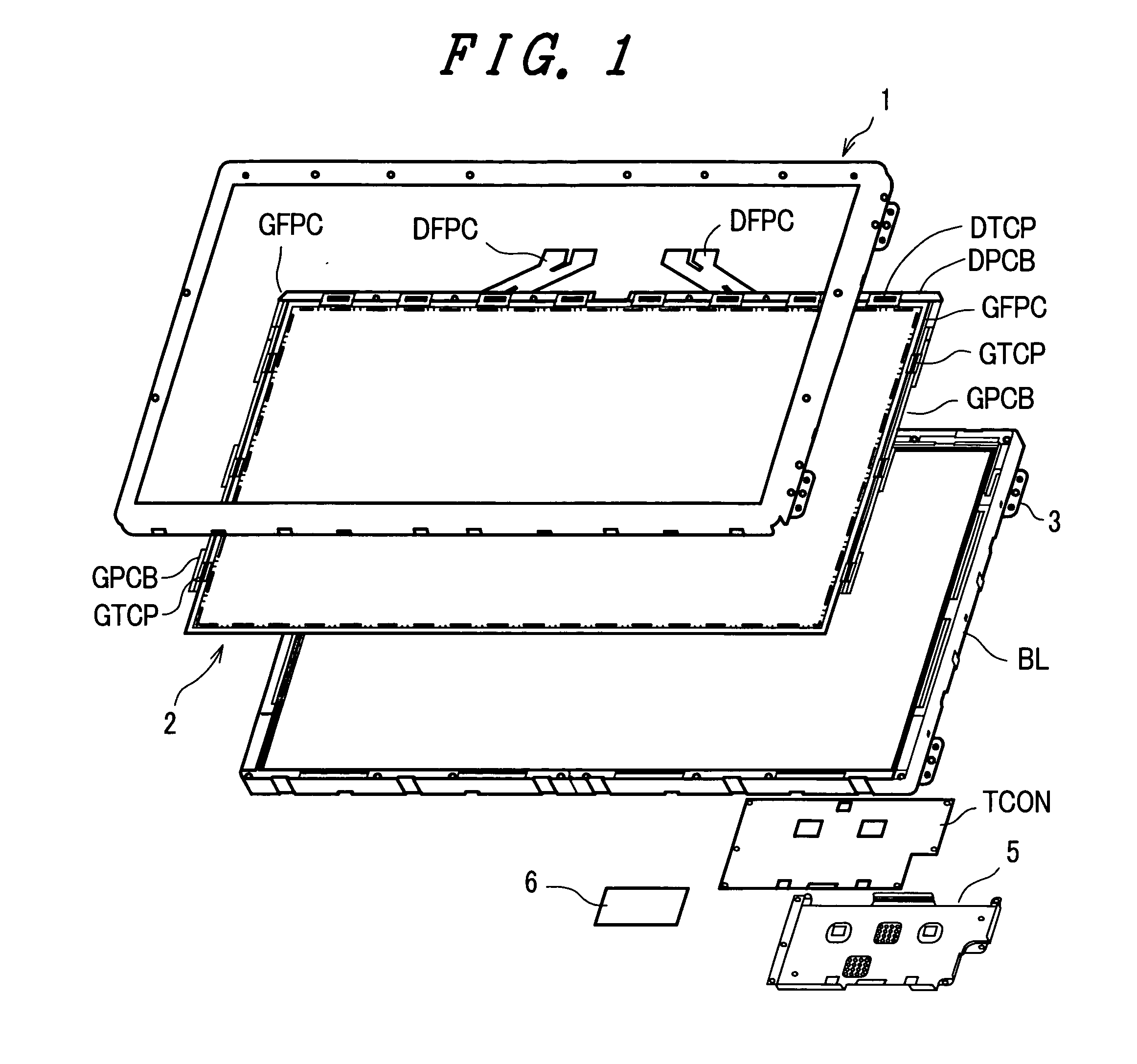
[0033]FIG. 1 is an exploded perspective view schematically showing the configuration of a liquid crystal display module of embodiment 1 of the present invention. As shown in this figure, the liquid crystal display module of the present embodiment is made up of a frame-like member or upper frame 1 made of a metal plate, a liquid crystal panel 2, and a backlight (BL). The upper frame 1 may also be referred to as the shield case, upper case, or upper metal frame.

[0034] The liquid crystal panel 2 has a pair of substrates, a drain printed circuit board (DPCB) arranged around the substrates, and two gate printed circuit boards (GPCBs). A liquid crystal layer is sandwiched between the substrates, which are made of a material having optical transparency and electrical insulation such as glass.

[0035] Tape carrier packages (DTCP and GTCP) are mounted on the printed circuit boards. Plural sets of liquid crystal-driving semiconductor integrated circuit elements forming driver ICs are Tape-Aut...

embodiment 2

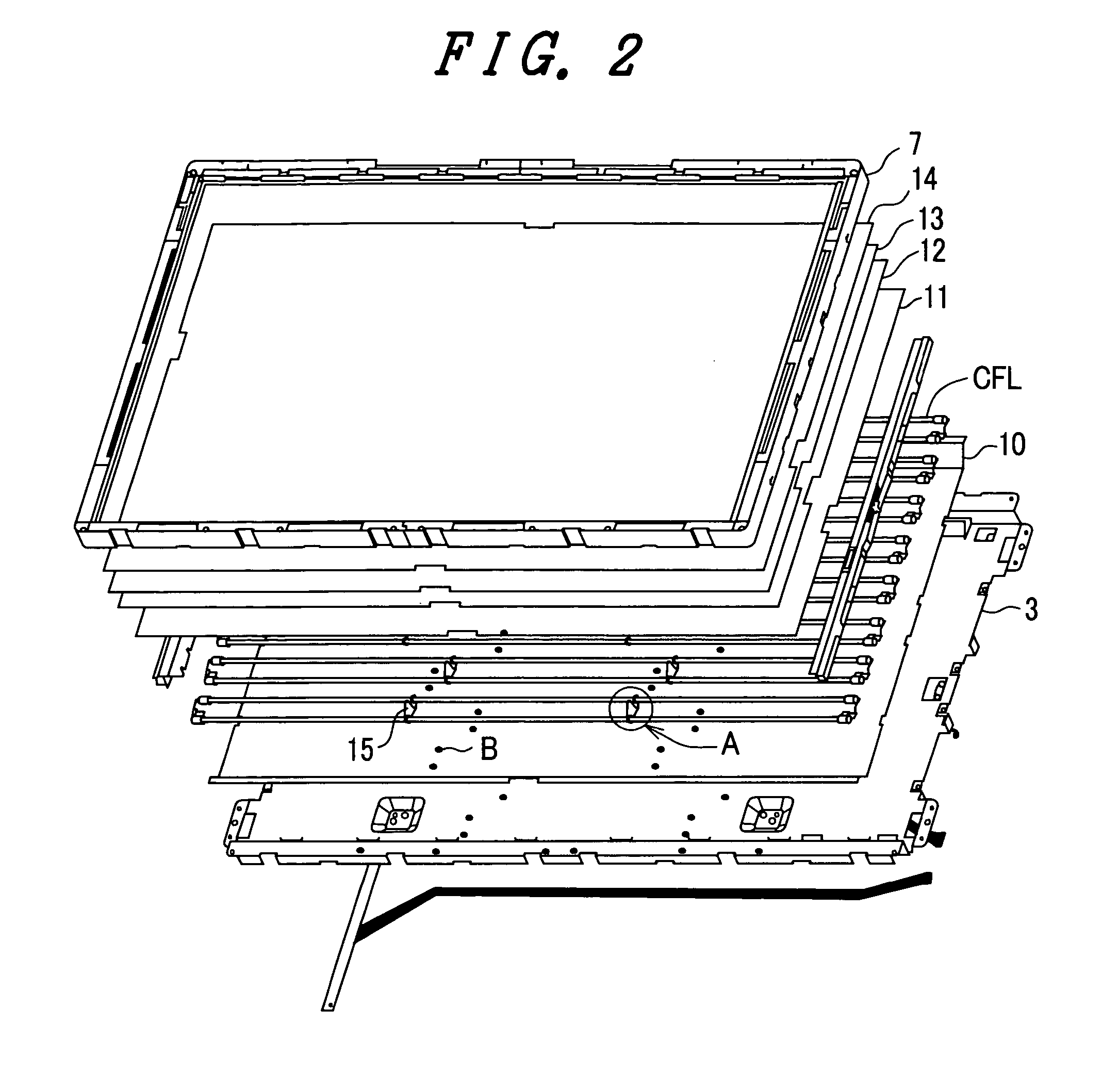
[0061]FIGS. 5A-5C are views schematically showing the structure of one lamp holder 15 of embodiment 2 of the present invention. FIG. 5A is a perspective view. FIG. 5B is a front elevation. FIG. 5C is a side elevation. As shown in FIGS. 5A, 5B, and 5C, the lamp holder 15 of the present embodiment also has a shock-absorbing material 26 mounted on the inner surfaces of its gripping portions 20 which make contact with cold cathode fluorescent tubes (CFLs), the shock-absorbing material 26 being made of silicone rubber, for example.

[0062] In the lamp holder 15 of the present embodiment, however, as shown in FIGS. 5A and 5B, a hole or slot 30 is formed between the gripping portion 20 and anchoring portion 22 at each end of the lamp holder 15, whereby resilience is imparted to the lamp holder itself. As indicated by numeral 31 in FIGS. 5A and 5B, the slot 30 has a bottom portion that is open on its upper side, i.e., on the side of the support portion 23.

[0063] Thus, in the present embodim...


PUM


Abstract

There is disclosed a liquid crystal display including cold cathode fluorescent tubes having improved failure resistance and shock resistance. The liquid crystal display has a liquid crystal panel and a backlight disposed on the opposite side of the display screen of the liquid crystal panel. The backlight has plural light sources and plural lamp holders for holding the light sources. Each of the lamp holders has a pair of gripping portions for gripping the light sources and a connector portion having the gripping portions at its opposite ends. The connector portion has slits in its opposite end portions, the slits extending in the longitudinal direction of the connector portion.

Description

BACKGROUND OF THE INVENTION [0001] 1. Field of the Invention [0002] The present invention relates to a liquid crystal display and, more particularly, to techniques effectively applied to a liquid crystal display having a right under type backlight. [0003] 2. Description of the Related Art [0004] Liquid crystal display modules are widely used as display devices for personal computers, monitors, television receivers, and so on. Such a liquid crystal display module is made up of a liquid crystal panel and a backlight for illuminating the panel. A drain driver and a gate driver are arranged around the panel. Backlights of this construction are classified into two major categories: side-light type backlight and right under type backlight. Liquid crystal display modules used as display devices for notebook personal computers mainly adopt side-light type backlights. [0005] In recent years, liquid crystal display modules have been increased in size to achieve larger display screens. Such la...

Claims


Application Information

Patent Timeline
IPC IPC(8): G02F1/1333F21S2/00F21S8/04F21V19/00F21Y103/00G02F1/1335G02F1/13357
CPCG02F1/133604G02F2201/503G02F2201/465G02F1/133608
Inventor KITADA, TAKAAKINISHIYAMA, SEIICHI
Owner HITACHI DISPLAYS
Why Eureka
Try Eureka