Tip to tail to center pointer

a pointer and tip technology, applied in the field of illumination pointers, can solve the problems of increasing complexity, increasing cost, reducing reliability, and directing light from multiple sources to the reflective surface of the pointer, and achieve the effect of eliminating differences in illumination level produced

Inactive Publication Date: 2005-07-28
SIEMENS VDO AUTOMOTIVE CORP
View PDF10 Cites 31 Cited by
  • Summary
  • Abstract
  • Description
  • Claims
  • Application Information

AI Technical Summary

Benefits of technology

[0010] The pointer is supported on a shaft that is rotated by a motor supported within a housing. A light source is disposed along the axis of rotation and mounted to a printed circuit board (PCB). The light source produces light that is transferred through a translucent shaft and toward the diffuser. The diffuser is received within a cavity of the pointer and is positioned such that a first reflective surface and a second reflective surface are aligned with light transmitted through the shaft. The light source is disposed along the axis such that rotation of the pointer does not change the relative orientation between the light source and the diffuser. The consistent relative orientation between the light source and the pointer substantially eliminates differences in illumination levels produced during rotation about the axis.

Problems solved by technology

Disadvantageously, such systems require either multiple light sources or a light guide.
Light emitted from multiple sources and directed onto reflective surfaces of the pointer provides undesirable variance in luminance levels as the pointer rotates.
Further the use of a light guide or multiple light sources increases complexity that in turn increases cost and reduces reliability.

Method used


Image

  • Tip to tail to center pointer
  • Tip to tail to center pointer
  • Tip to tail to center pointer

Examples


Embodiment Construction

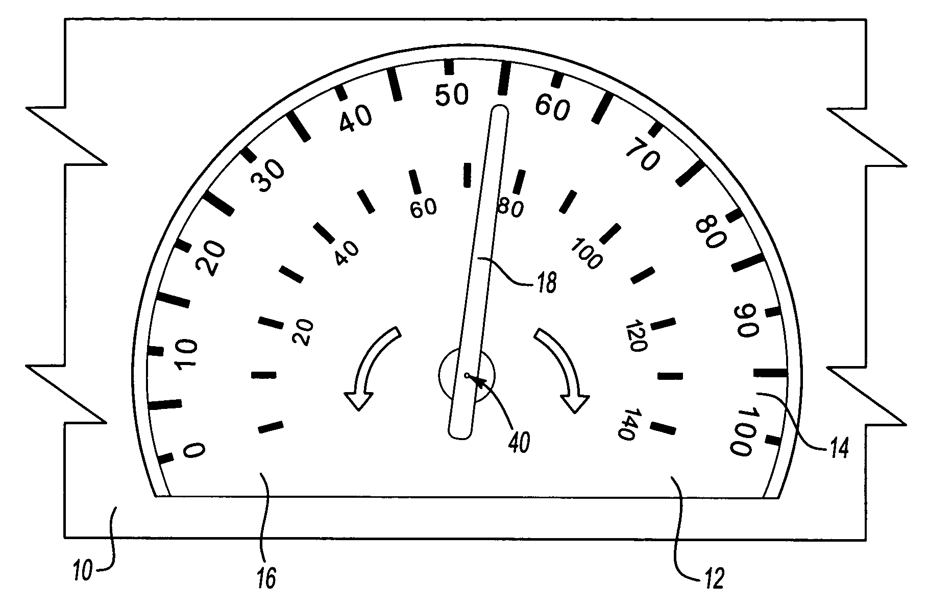
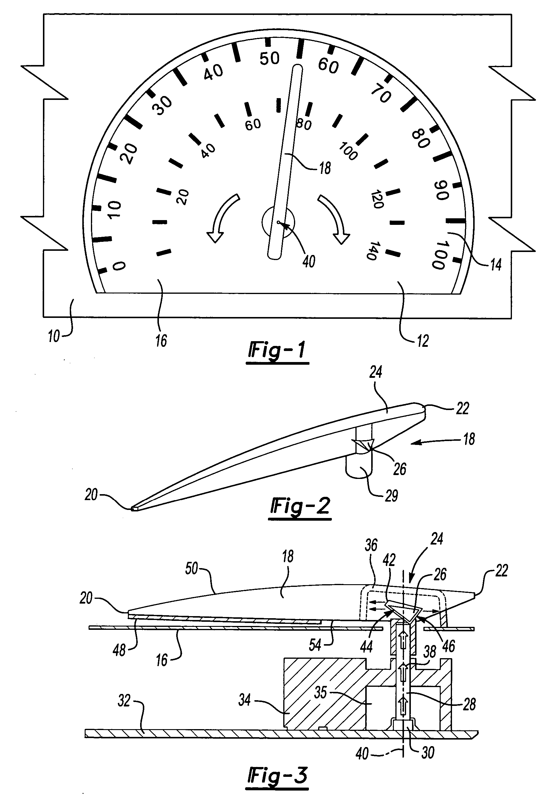
[0024] Referring to FIG. 1 an instrument panel 10 includes a speedometer 12. The speedometer 12 includes a graphical image 16 that includes a scale 14 disposed radially about an axis of rotation 40. A pointer 18 rotates about the axis 40 to point to a specific number on the scale 14. The pointer 18 is illuminated to provide a desirable visual reference on the scale 14. As appreciated, although a speedometer 12 is shown, other gauges that are known to those skilled in the art are also within the contemplation of this invention.

[0025] Referring to FIG. 2, the pointer 18 provides consistent lighting throughout the entire range of movement along the speedometer 12. The pointer 18 is a generally elongated rectangular member including a tip 20, a tail 22 and a center 24. The pointer 18 is supported atop a shaft adaptor 29. Light is emitted through the pointer 18 from the center 24 toward the tip 20 and toward the tail 22. The pointer 18 includes a first reflective surface 44 and a second...


PUM


Abstract

A pointer includes a diffuser that receives light from a single light source and reflects light toward a tip and a tail of the pointer uniformly regardless of radial position. Transmission of light toward a tip and a tail of the pointer is accomplished by a reflective surfaces within the pointer. A diffuser is disposed adjacent the reflective surfaces to provide an even luminance throughout the pointer. The light source produces light that is transferred through a translucent shaft toward the diffuser. The diffuser is aligned with light transmitted through the shaft. The light source is disposed along the axis such that rotation of the pointer does not change the relative orientation between the light source and the reflective surfaces. The consistent relative orientation between the light source and the pointer substantially eliminates differences in illumination levels produced during rotation about the axis.

Description

[0001] The application claims priority to U.S. Provisional Application No. 60 / 538,488 which was filed on Jan. 22, 2004.BACKGROUND OF THE INVENTION [0002] This invention generally relates to an illuminated pointer for an instrument panel. More particularly, this invention relates to an illuminated pointer that provides consistent and continuous luminance along the entire length of the pointer utilizing a single light source. [0003] An Instrument panel for a vehicle includes several gauges for displaying and conveying information to a driver. The instrument panel typically includes a speedometer along with other gauges such as a tachometer, battery level indicator, and oil pressure gauge. Typically a pointer is mounted to move relative to a fixed graphical image on each gauge. [0004] The pointer is typically one of two basic types, either a non-active pointer or an active pointer. A non-active pointer is illuminated by a light source mounted to a circuit board positioned behind a ligh...

Claims


Application Information

Patent Timeline
Patent Type & Authority Applications(United States)
IPC IPC(8): G01D13/26
CPCG01D13/265B60K2370/6992
Inventor LEE, CHAYBIRMAN, VYACHESLAV B.ECKARDT, WERNER
Owner SIEMENS VDO AUTOMOTIVE CORP
Why Eureka
Try Eureka