Optical disk, method for recording and reproducing write-once information on and from optical disk, optical disk reproducing device, optical disk recording and reproducing device, device for recording write-once information on optical disk, and optical disk recording device

Inactive Publication Date: 2005-07-28
PANASONIC CORP
View PDF26 Cites 47 Cited by
  • Summary
  • Abstract
  • Description
  • Claims
  • Application Information

AI Technical Summary

Benefits of technology

[0045] A second method for reproducing write-once information from an optical disk (a) comprising a disk substrate; and a recording layer on the disk substrate, the recording layer including a film that can be reversibly changed between two optically detectable states; and (b) storing write-once information formed by first recording areas and second recording areas with different reflection coefficients in a pre-determined portion of the recording layer; comprises irradiating focused laser light onto the pre-determined portion; and detecting a change in a luminous energy reflected from the disk. In accordance with this second method for reproducing write-once information from an optical disk, the write-once information can be reproduced easily.
[0046] A first configuration of an apparatus for reproducing optical disks comprising (a) a main information recording area for recording main information; and (b) an auxiliary signal recording area overlapping partly with the main information recording area for recording a phase-encoding modulated auxiliary signal that overlaps a signal of main information, comprises means for reproducing a main information signal in the main information recording area with an optical head; first decoding means for decoding a main information signal to obtain main information data; means for reproducing a mixed signal comprising a main information signal in the auxiliary signal recording area and the auxiliary signal as a reproduction signal with the optical head; frequency separation means for suppressing the main information signal in the reproduction signal to obtain the auxiliary signal; and second decoding means for phase-encoding decoding the auxiliary signal to obtain the auxiliary data. In accordance with this first configuration of an apparatus for reproducing optical disks, the decoding data of the auxiliary signal can be reproduced reliably.
[0047] It is preferable that in the apparatus for reproducing optical disks according to the first configuration, the frequency separation means is a low-frequency component separation means for suppressing high frequency components in the reproduction signal reproduced with the optical head to obtain a low frequency reproduction signal, and that the apparatus further comprises a second-slice-level setting portion for producing a second slice level from the low-frequency reproduction signal; and a second-level slicer for slicing the low-frequency reproduction signal at the second slice level to obtain a binarized signal; wherein the apparatus phase-encoding decodes the binarized signal to obtain the auxiliary data. With this configuration, errors due to variations of the envelope of the reproduction signal of the write-once information can be prevented. In this case, it is preferable that the second-slice-level setting portion comprises auxiliary low-frequency component separation means with a time constant that is larger than that of the low-frequency component separation means; a reproduction signal reproduced with the optical head or a low-frequency reproduction signal obtained with the low-frequency compone

Problems solved by technology

With the above configuration, it is possible to record disk information in TOC (or control data) areas, but when disk data is recorded with pre-pits, the disk information has to be administered stamper by stamper and cannot be administered user by user.
Moreover, when

Method used


Image

  • Optical disk, method for recording and reproducing write-once information on and from optical disk, optical disk reproducing device, optical disk recording and reproducing device, device for recording write-once information on optical disk, and optical disk recording device
  • Optical disk, method for recording and reproducing write-once information on and from optical disk, optical disk reproducing device, optical disk recording and reproducing device, device for recording write-once information on optical disk, and optical disk recording device
  • Optical disk, method for recording and reproducing write-once information on and from optical disk, optical disk reproducing device, optical disk recording and reproducing device, device for recording write-once information on optical disk, and optical disk recording device

Examples


Example

FIRST EMBODIMENT

[0113] First of all, the structure of a magneto-optical disk is explained.

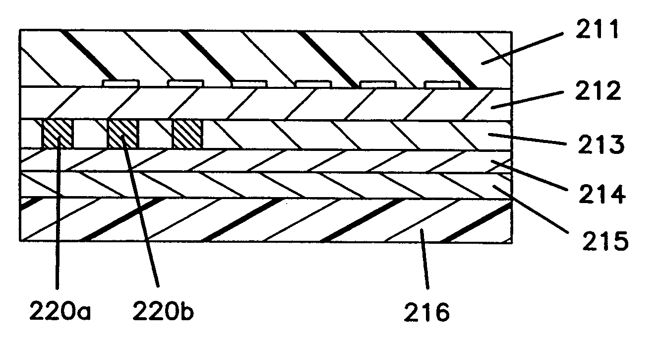
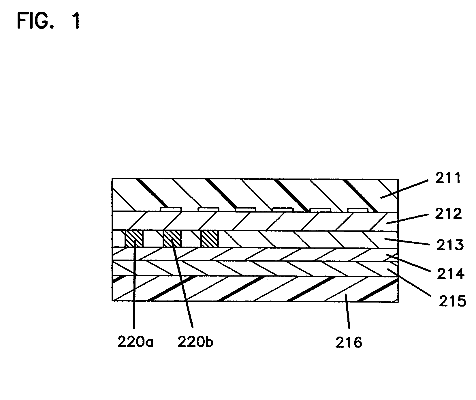
[0114]FIG. 1 is a cross-section showing the structure of a magneto-optical disk in a first embodiment of the present invention. As is shown in FIG. 1, a dielectric layer 212 is formed on top of a disk substrate 211, and a recording layer 213 is formed on top of the dielectric layer 212. In the recording layer 213, a plurality of BCA portions 220a and 220b (BCA is one of the formats for write-once identification information) is recorded in a circumferential direction of the disk. On top of the recording layer 213, an intermediate dielectric layer 214 and a reflecting layer 215 are deposited in that order. An overcoat layer 216 is formed on top of the reflecting layer 215.

[0115] Referring to FIG. 8, the following is an explanation of a method for producing a magneto-optical disk in accordance with this embodiment.

[0116] First of all, as shown in FIG. 8 (1), a disk substrate 211, which has gui...

Example

SECOND EMBODIMENT

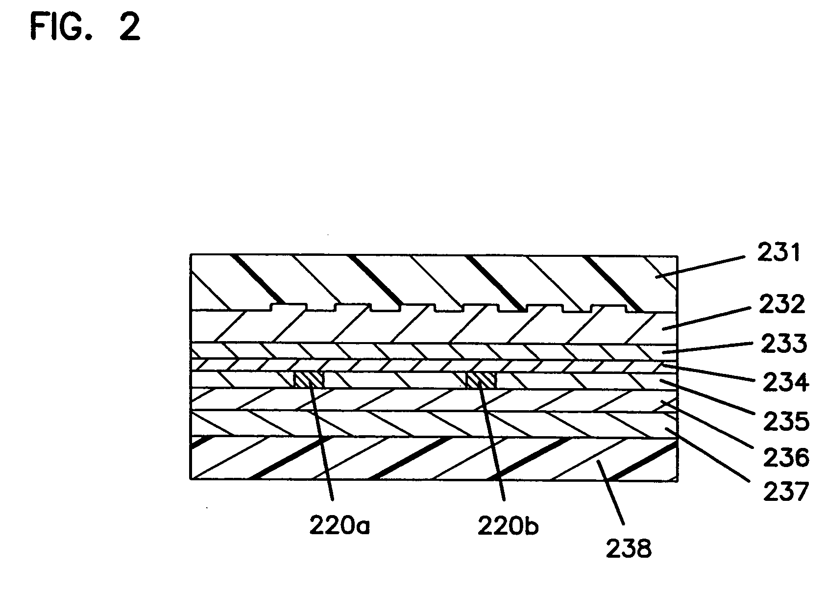
[0135]FIG. 2 is a cross-section showing the structure of a magneto-optical disk in a second embodiment of the present invention. As is shown in FIG. 2, a dielectric layer 232 is formed on top of a disk substrate 231, and a tri-layer recording layer comprising a magnetic reproduction film 233, an intermediate magnetic film 234, and a magnetic recording film 235 is formed on top of the dielectric layer 232. In the recording layer, a plurality of BCA portions 220a and 220b is recorded in a circumferential direction of the disk. On top of the recording layer, an intermediate dielectric layer 236 and a reflecting layer 237 are deposited in that order. An overcoat layer 238 is formed on top of the reflecting layer 237.

[0136] Referring to FIG. 8 of the first embodiment and to FIG. 9, the following is an explanation of a method for producing a magneto-optical disk in accordance with this embodiment.

[0137] First of all, a disk substrate 231, which has guide grooves or pre...

Example

THIRD EMBODIMENT

[0147]FIG. 40 is a cross-section showing the structure of a magneto-optical disk in a third embodiment of the present invention. As is shown in FIG. 40, a dielectric layer 302 is formed on top of a disk substrate 301, and a recording layer 303 of a phase-hangeable material that can reversibly change between a crystal phase and an amorphous phase is formed on top of the dielectric layer 302. In the recording layer 303, a plurality of BCA portions 310 is recorded in a circumferential direction of the disk. On top of the recording layer 303, an intermediate dielectric layer 304 and a reflecting layer 305 are deposited in that order. An overcoat layer 306 is formed on top of the reflecting layer 305. Two optical disks, of which only the first disk has the overcoat layer 306 are laminated by adhesion layer 307. It is also possible to laminate together two optical disks of the same configuration by hot-melting.

[0148] The following is an explanation of a method for produc...


PUM


Abstract

An optical disk storing write-once information usable for protecting the copyright of the software by preventing the duplication, unauthorized use, etc., of the software. In the optical disk, a recording layer (213) is formed on a disk substrate (211) with a dielectric layer (212) inbetween. Then, an intermediate dielectric layer (214) and a reflecting layer (215) are successively laminated upon the recording layer (213), and an overcoat layer (216) is formed on the surface of the reflecting layer (215). A plurality of BCA (one of write-once identification information systems) sections (220a and 220b) are recorded by lowering the vertical magnetic anisotropy of the recording layer (213). At the time of reproduction, the write-once information is detected from differential signals.

Description

FIELD OF THE INVENTION [0001] The present invention relates to an optical disk for recording, reproducing and erasing information. In particular, the present invention relates to an optical disk comprising write-once information that can be used for copyright protection, for example for copy-protection or protection from unauthorized use of software. Throughout this specification, “write-once information” refers to information that is recorded after finishing the disk manufacturing process. The present invention relates further to a method for recording and a method for reproducing write-once information on the optical disk, an apparatus for reproducing the optical disk, an apparatus for recording and reproducing the optical disk, an apparatus for recording write-once information on the optical disk, and an apparatus for recording on the optical disk. BACKGROUND OF THE INVENTION [0002] In recent years, the speed with which electronic calculators and information processing systems ca...

Claims


Application Information

Patent Timeline
IPC IPC(8): G11B11/10G06T1/00G11B7/0037G11B7/0045G11B7/007G11B7/24G11B11/105G11B20/00G11B20/10G11B20/12G11B23/28G11B23/40
CPCG06T1/0021G11B2020/1245G11B7/0037G11B7/0045G11B7/00736G11B7/24G11B11/10506G11B11/10515G11B11/10584G11B11/10595G11B20/00086G11B20/00123G11B20/00166G11B20/00181G11B20/0021G11B20/00231G11B20/0026G11B20/00268G11B20/00347G11B20/00876G11B20/00884G11B20/10G11B20/1217G11B20/1258G11B23/281G11B23/288G11B23/40G11B2020/122G11B2020/1244G06T2201/0064G11B11/10
Inventor OSHIMA, MITSUAKIKONISHI, SHINICHITANAKA, SHIN-ICHIKOISHI, KENJIMORIYA, MITSUROUGOTOH, YOSHIHOTAKEMURA, YOSHINARIMIYATAKE, NORIOMURAKAMI, MOTOYOSHI
Owner PANASONIC CORP
Why Eureka
Try Eureka