Network switching device and method using shared buffer

a network switching and buffer technology, applied in data switching networks, digital transmission, instruments, etc., can solve the problems of large memory space consumed by buffers, reduced memory efficiency, and large memory capacity of devices, and achieve the effect of high memory use efficiency in buffering variable-length packets

Inactive Publication Date: 2005-07-28
SOCIONEXT INC
View PDF10 Cites 39 Cited by
  • Summary
  • Abstract
  • Description
  • Claims
  • Application Information

AI Technical Summary

Benefits of technology

[0018] In view of the foregoing, it is an object of the present invention to provide a network switching device that prevents its shared buffer from suffering a blocking problem, while achieving a higher memory use efficiency in buffering variable-length packets.

Problems solved by technology

A drawback of the network switching device shown in FIG. 15 is that the device demands a large memory capacity since it has to reserve a number of buffer areas in its memory space to provide a dedicated buffer for each receive port and transmit port.
Nevertheless, the buffer consumes large amounts of memory space, which equals the maximum packet length multiplied by the maximum number of packets to be stored.
In this case, a large portion of the buffer remains unused, meaning that the memory efficiency decreases.
In this situation, some other ports could suffer a decrease of throughput as a result of congestion inside the shared buffer, although the ports are supposed to work independently of each other.
However, as mentioned earlier, the problem with this configuration is that a large buffer capacity is required, and it leads to an increased component cost.
Those devices, however, lack the ability to avoid a blocking problem.

Method used


Image

  • Network switching device and method using shared buffer
  • Network switching device and method using shared buffer
  • Network switching device and method using shared buffer

Examples


Embodiment Construction

[0039] Preferred embodiments of the present invention will be described below with reference to the accompanying drawings, wherein like reference numerals refer to like elements throughout.

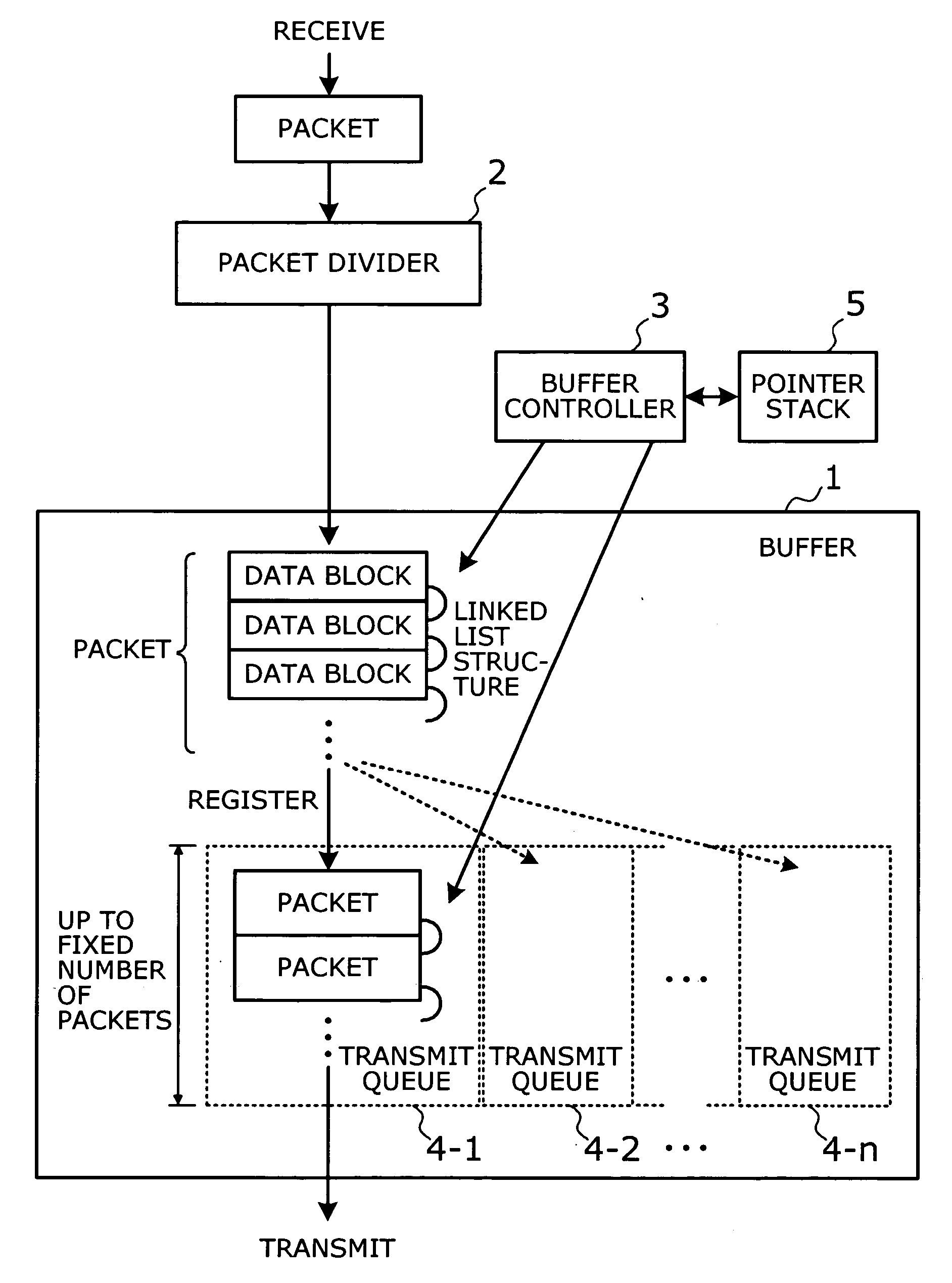
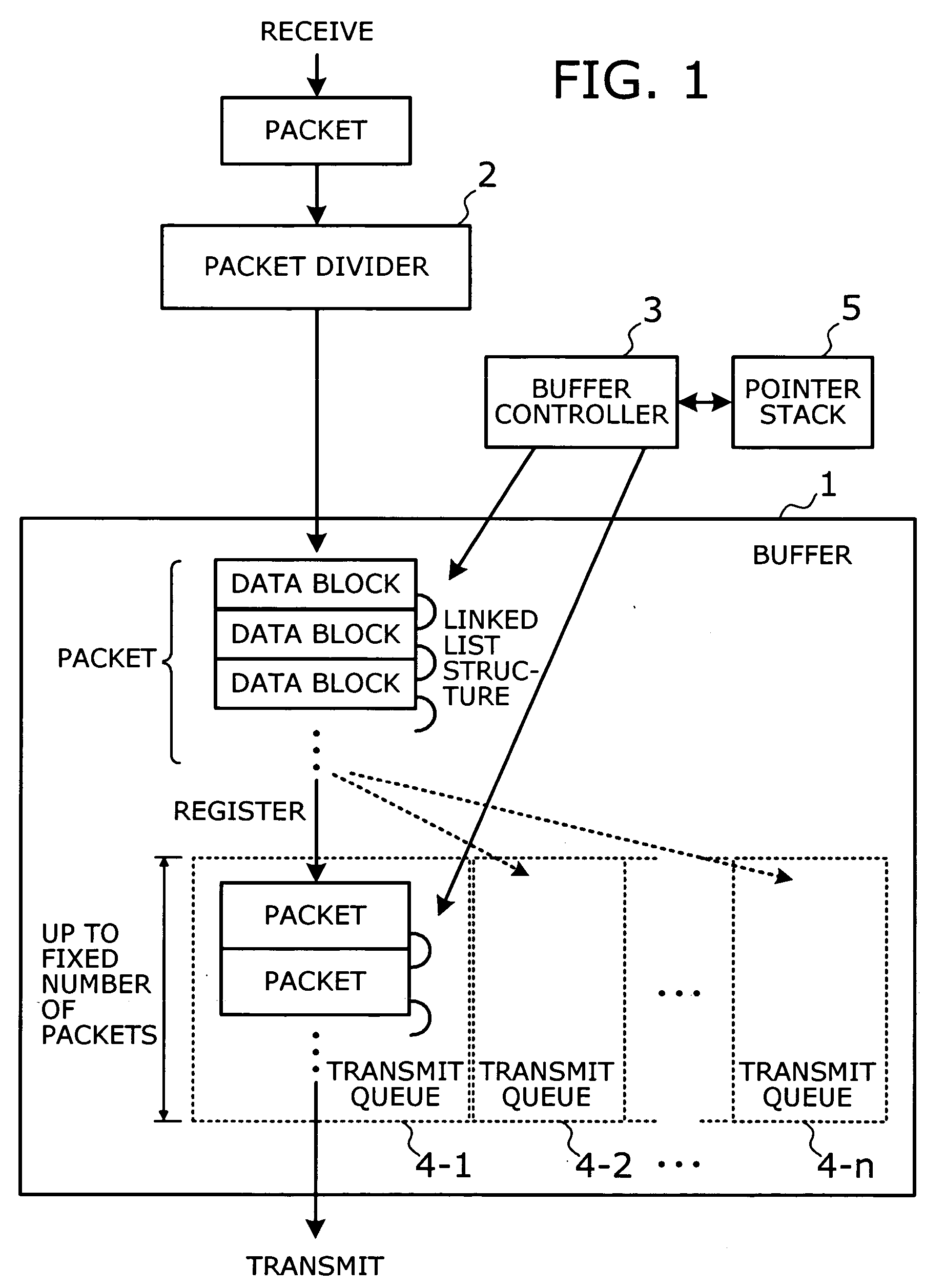
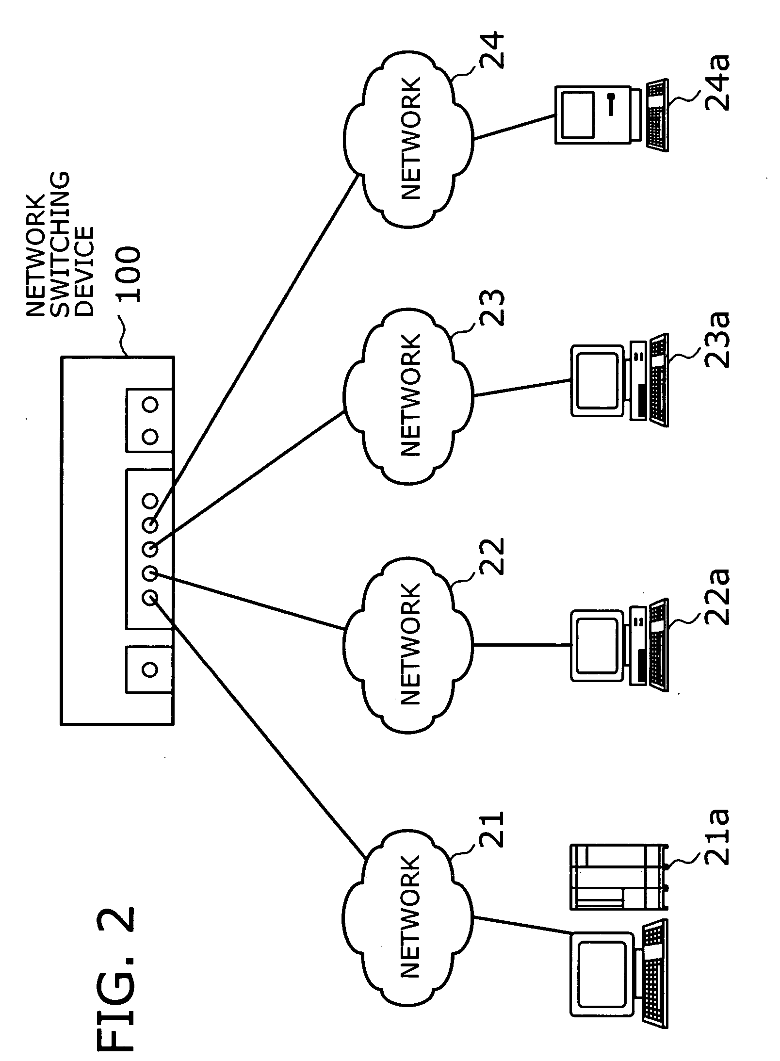
[0040]FIG. 1 is a conceptual view that shows the principle of the present invention. The network switching device of the present invention is connected to a plurality of networks where messages are communicated in the form of variable-length packets, so that the device transports packets between those networks. As shown in FIG. 1, this network switching device has a buffer 1, a packet divider 2, and a buffer controller 3.

[0041] The buffer 1 is a storage device (e.g., semiconductor memory) for storing received packets. The packet divider 2 divides each received packet into one or more fixed-length data blocks and supplies them to the buffer 1. This means that one data block is smaller than the maximum data size that a single packet allows. The buffer controller 3 controls read and write operation...


PUM


Abstract

A network switching device that prevents its shared buffer from suffering a blocking problem, while achieving a higher memory use efficiency in buffering variable-length packets. Every received packet is divided into one or more fixed-length data blocks and supplied to the buffer. Under the control of a buffer controller, a transmit queue is created to store up to a fixed number of data blocks for each different destination network, and the data blocks written in the buffer are registered with a transmit queue corresponding to a given destination. The linkage between data blocks in each packet, as well as the linkage between packets in each transmit queue, is managed as a linked list structure based on the locations of data blocks in the buffer.

Description

[0001] This application is continuing application, filed under 35 U.S.C. §111(a), of International Application PCT / JP2003 / 000436 filed Jan. 20, 2003.BACKGROUND OF THE INVENTION [0002] 1. Field of the Invention [0003] The present invention relates to a network switching device and a network switching method for transferring variable-length packets between a plurality of networks. More particularly, the present invention relates to a network switching device and a network switching method using a shared buffer as temporary packet storage. [0004] 2. Description of the Related Art [0005] Network switching devices are often used to interconnect many network segments, as in the Internet and other large-scale networks. The most widely used are those with an internal buffer to temporarily store received packets and ispect their integrity of the received packets before directing them to intended destination ports. This type of switching mechanism is called “store and forward” switching. In m...

Claims


Application Information

Patent Timeline
Patent Type & Authority Applications(United States)
IPC IPC(8): H04L47/43G06F13/38H04L13/08H04L47/32H04L49/9015
CPCH04L12/5693H04L49/103H04L49/508H04L49/9042H04L49/90H04L49/9021H04L49/552H04L47/50
Inventor KATAYAMA, TAUL
Owner SOCIONEXT INC
Why Eureka
Try Eureka