Microfluidic chemostat

a technology of microfluidic chemostat and chemostat, which is applied in the field of microfluidic chemostat, can solve the problems of difficult to produce microfluidic chemostat synthetically for medical treatment, inexact measurement of plating, and inability to grow at an unknown ra

Inactive Publication Date: 2005-07-28
CALIFORNIA INST OF TECH
View PDF73 Cites 88 Cited by
  • Summary
  • Abstract
  • Description
  • Claims
  • Application Information

AI Technical Summary

Benefits of technology

[0010] Embodiments of the invention include a chemostat. The chemostat may include a growth chamber having a plurality of compartments, where each of the compartments may be fluidly isolated from the rest of the growth chamber by one or more actuatable valves. The chemostat may also include a nutrient supply-line to supply growth medium to the growth chamber, and an output port to remove fluids from the growth chamber.

Problems solved by technology

The chemical complexity of pharmaceutical proteins makes it difficult to produce them synthetically for medical treatments.
Unfortunately, plating can produce inexact measurements because the culture continues to grow at an unknown rate during the period of dilution in preparation for plating.
However, this technique is a hands-on, serial process that is prone to human error.
Although the counter is rapid and accurate, it is also expensive and subject to a number of artifactual complications.
Moreover, the pore through which the suspension is pumped is prone to clogging if the media and diluents are not carefully prepared.
This technique is time consuming and requires a considerable amount of sacrificial culture.
As such, it is unsuitable for routine monitoring of the growth rate.
Data collection with conventional chemostats is not easy to automate, which makes studies and measurements of the bacterial cultures labor intensive.
The devices also consume large amounts of growth medium that increase the cost of experiments, especially when costly reagents have to be used.
Another difficulty with chemostats is their tendency to form biofilms on growth-chamber walls and probe surfaces.
Once started, the biofilms are difficult to remove and may consume a significant fraction of the substrate.
This may compromise the fixed biomass fundamental conservation principle of the chemostat, inducing hybrid batch / chemostat characteristics.

Method used


Image

  • Microfluidic chemostat
  • Microfluidic chemostat
  • Microfluidic chemostat

Examples


Embodiment Construction

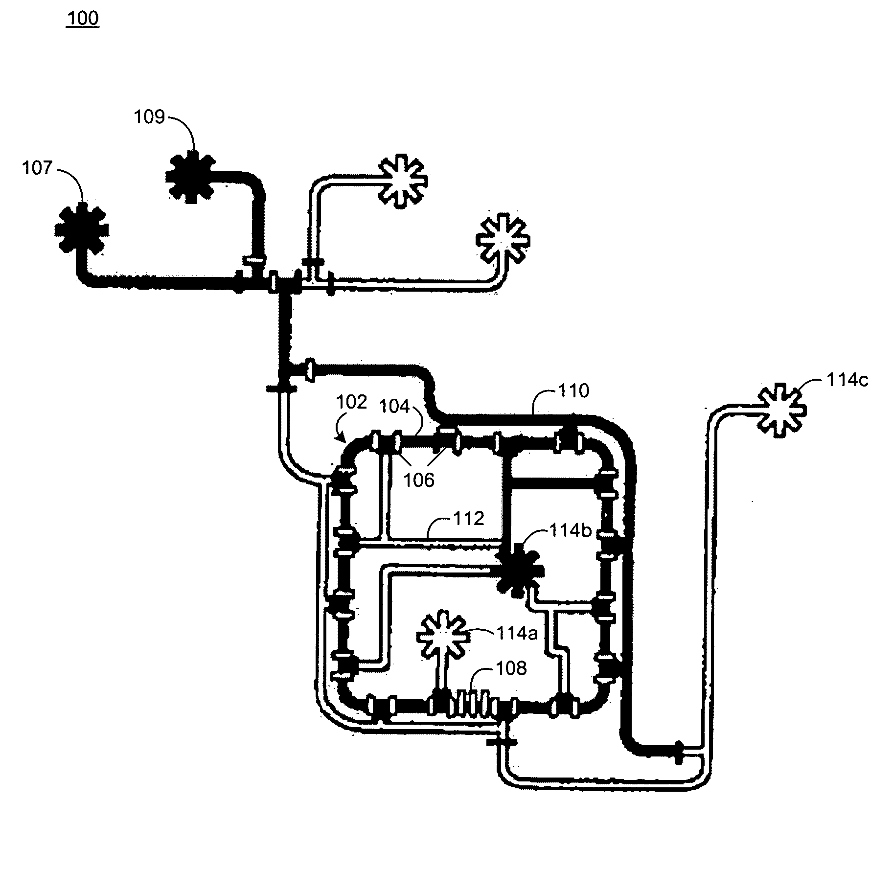
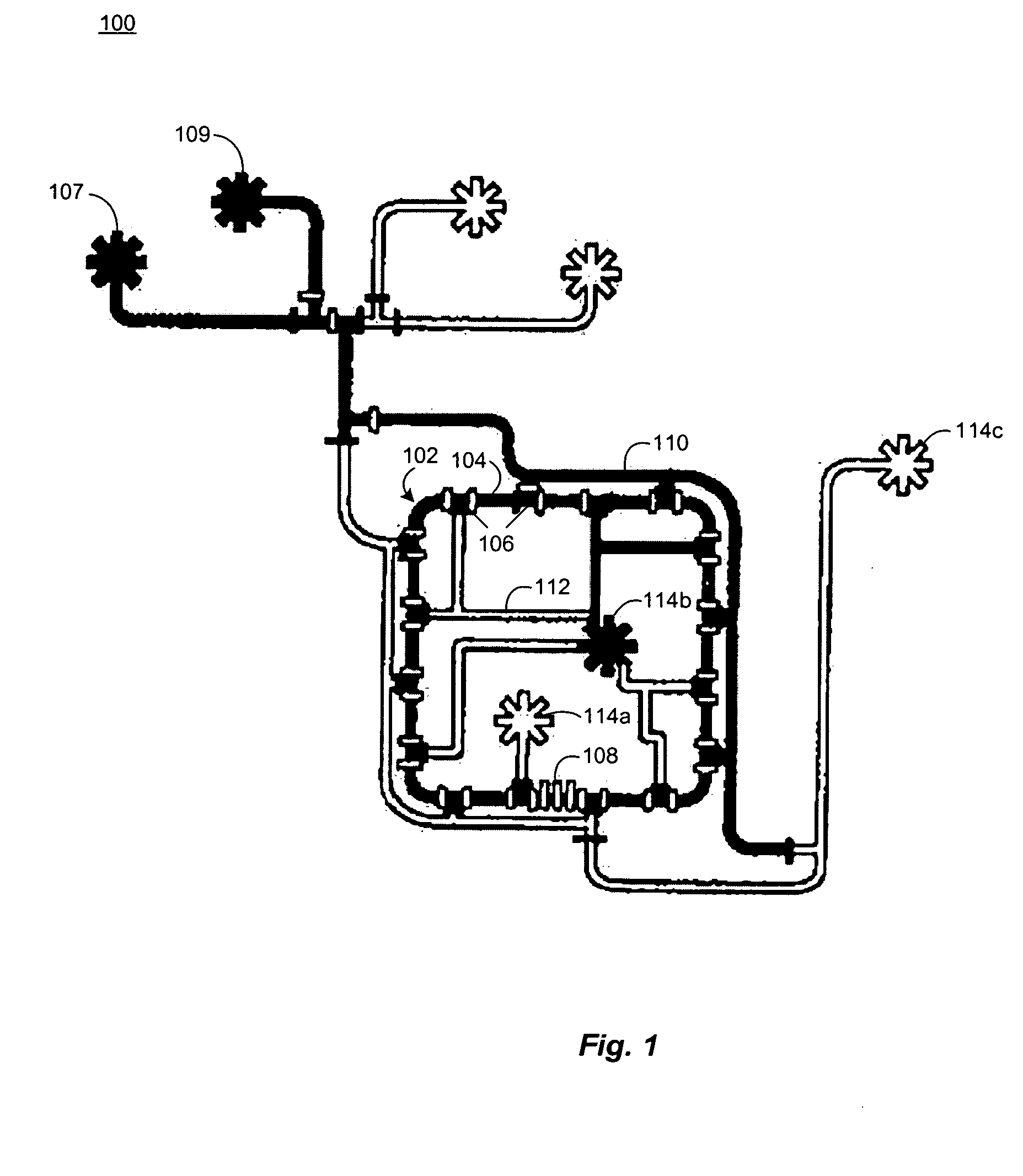
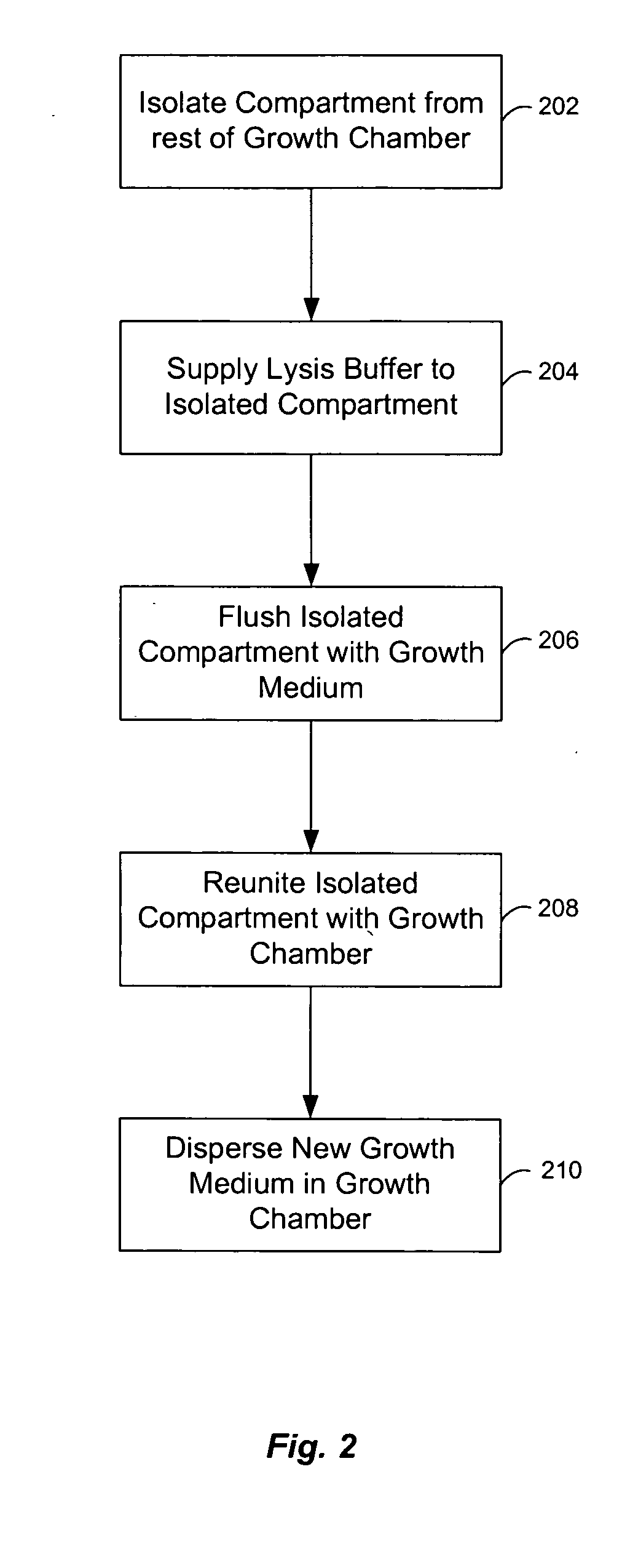
[0062] Chemostats of the present invention include microfluidic chemostats having growth chambers divided into two or more compartments. These chemostats can operate with low quantities of growth reagents / medium, which reduces the costs of the chemostat experiments. They may also be operated such that discrete cleaning of the chemostat compartments can occur while an experiment is being conducted, which reduces or prevents the formation of biofilms on the walls of the device.

[0063] The small size of the microfluidic chemostats of the invention have high surface area to volume ratio (e.g., about 100 times the surface area to volume ratio of a conventional chemostat). The high ratio permits a larger percentage of the growth chamber surface (e.g., about 55% of the surface or more) to serve as a diffusion interface for the diffusion of gases such as oxygen (O2) and carbon dioxide (CO2). The gas diffusion may be further enhanced by constructing the growth chamber out of materials that h...


PUM

PropertyMeasurementUnit
volumeaaaaaaaaaa
volumeaaaaaaaaaa
thicknessaaaaaaaaaa

Abstract

A chemostat that includes a growth chamber having a plurality of compartments, where each of the compartments may be fluidly isolated from the rest of the growth chamber by one or more actuatable valves. The chemostat may also include a nutrient supply-line to supply growth medium to the growth chamber, and an output port to remove fluids from the growth chamber. Also, a method of preventing biofilm formation in a growth chamber of a chemostat. The method may include the steps of adding a lysis agent to a isolated portion of the growth chamber, and reuniting the isolated portion with the rest of the growth chamber.

Description

CROSS-REFERENCES TO RELATED APPLICATIONS [0001] This application claims the benefit of U.S. Provisional Application No. 60 / 536,863, filed Jan. 16, 2004, entitled “MICROFLUIDIC CHEMOSTAT” the entire contents of which are herein incorporated by this reference.STATEMENT AS TO RIGHTS TO INVENTIONS MADE UNDER FEDERALLY SPONSORED RESEARCH OR DEVELOPMENT [0002] This material is based upon work supported by the Defense Advanced Research Projects Agency (Grant No. N66001-02-1-8929), and the National Science Foundation under Grant No. CTS.0088649. The U.S. Government may therefore have certain rights in the invention.BACKGROUND OF THE INVENTION [0003] The chemical complexity of pharmaceutical proteins makes it difficult to produce them synthetically for medical treatments. For many of these proteins, the only practical production route is to grow bacterial cultures that have been designed to produce the protein in adequate quantities. Thus, pharmaceutical manufacturers, among others, have an ...

Claims


Application Information

Patent Timeline
Patent Type & Authority Applications(United States)
IPC IPC(8): B01L3/00C12M1/00C12M1/113C12M1/18C12M3/00C12P19/04C12P19/34C12Q1/02C12Q1/68
CPCB01L3/5027B01L3/502738B01L2300/0861B01L2300/0877B01L2300/10C12M39/00B01L2400/0481B01L2400/0655C12M23/16C12M23/34B01L2300/163C12P1/00C12P19/04
Inventor BALAGADDE, FREDERICKHANSEN, CARL L.KARTALOV, EMILQUAKE, STEPHEN R.
Owner CALIFORNIA INST OF TECH
Why Eureka
Try Eureka